Product Description
Product Description
We has been providing genuine and high quality starters at the lowest possible cost in China, and got a high reputation from our clients due to the reliable quality, competitive price and on-time delivery.
1.Durable and high Quality.
2.Nice-looking packing.
3.Prompt delivery.
4.Wide range of parts for more models available.
5.Most competitive wholesale prices.
6.One stop buying service provided.
| car brand | made in China |
| engine type | Diesel engines |
| car model | universal |
| Material | casting |
| type | Machinery |
| installation method | direct installation |
| Scope of application | standard |
| effect | internal combustion engine |
| trademark | OEM |
| ordering method | customized |
| order cycle | 2-5day |
| ignition method | Compression ignition |
| product quality | high quality |
| main market | africa asia |
| Main models | universal |
Product Recommended
Company Profile
Packaging & Shipping
FAQ
1. Is this product new?
All our products are brand new and original, so each product can be strictly tested, please rest assured to buy.
2. Do you offer custom designs?
Custom design is support for customization. We have very rich experience in product customization.
3. Delivery time?
It can be shipped on the same day, special models need to be customized by the factory, we will ship within 15-30 days, without affecting the delivery time. If you have any questions or concerns, please contact us directly for assistance.
4. How to clean the injector?
(1) Remove the injector from the engine;
(2) Connect the carburetor to clean the fuel tank and the fuel injector with a special connector;
(3) Inject the carburetor cleaner into the fuel injector, and check whether the fuel injector leaks when it is not powered on;
(4) Intermittently energize the electromagnetic coil of the fuel injector, let the carburetor cleaner clean the fuel injector, and observe its spray atomization at the same time.
5. How to test the injector?
Detect dripping water from the injector. Select the connector of the tester according to the fuel injector model and connect it well, then check the sealing O-ring group (replace if found damaged), install the fuel injector on the test stand, press the fuel pump button, and adjust the pressure to the vehicle under test Factory specified pressure (preferably higher than 10%), observe whether the injector drips oil. If the leakage is more than 1 drop within 1min (or according to the technical standard), replace the fuel injector.
/* January 22, 2571 19:08:37 */!function(){function s(e,r){var a,o={};try{e&&e.split(“,”).forEach(function(e,t){e&&(a=e.match(/(.*?):(.*)$/))&&1
| Application: | Motor, Electric Cars, Motorcycle, Machinery, Marine, Agricultural Machinery, Car |
|---|---|
| Function: | Distribution Power, Clutch, Change Drive Torque, Change Drive Direction, Speed Changing, Speed Reduction, Speed Increase |
| Layout: | Three-Ring |
| Hardness: | Soft Tooth Surface |
| Installation: | Torque Arm Type |
| Step: | Stepless |
Can you provide examples of machinery that use bevel gears?
Bevel gears are widely used in various machinery and mechanical systems where torque transmission and direction changes are required. These gears are specifically designed to transmit power between intersecting shafts at different angles. Here are some examples of machinery and equipment that commonly use bevel gears:
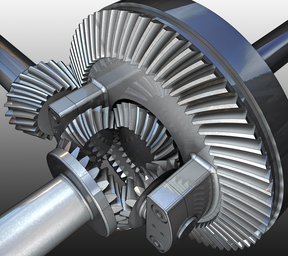
- Automotive Industry: Bevel gears are extensively used in automotive applications. They can be found in different parts of vehicles, including the differential gear system, powertrain components, steering systems, and transfer cases. In the differential, bevel gears help distribute torque between the drive wheels while allowing them to rotate at different speeds during turns.
- Aerospace Industry: Bevel gears are utilized in various aerospace applications, such as aircraft engines, landing gear systems, and helicopter transmissions. They play a critical role in transferring power and changing the direction of rotation in these high-performance systems.
- Industrial Machinery: Bevel gears are commonly employed in industrial machinery and equipment. They are used in gearboxes, speed reducers, and power transmission systems. Examples include conveyors, mixers, pumps, packaging machinery, printing presses, and textile machinery. Bevel gears allow efficient power transmission and enable the machinery to operate at different speeds and directions as required by the specific application.
- Construction and Heavy Equipment: Bevel gears are found in construction equipment such as cranes, excavators, loaders, and bulldozers. They are integral components of the drivetrain systems, enabling the transfer of power and torque to the wheels or tracks, as well as facilitating steering and movement of the equipment.
- Marine Applications: Bevel gears are utilized in various marine applications, including propulsion systems, marine generators, winches, steering mechanisms, and anchor handling equipment. They help transmit power efficiently and withstand the challenging marine environment.
- Machine Tools: Bevel gears are employed in machine tools such as milling machines, lathes, and grinders. They are essential for transmitting power and facilitating the required speed and direction changes in these precision machining systems.
- Power Plants: Bevel gears are used in power generation facilities, including wind turbines, hydroelectric turbines, and steam turbines. They play a crucial role in converting the rotational motion of the turbine blades into electrical energy by transmitting torque to the generator.
- Mining and Material Handling: Bevel gears are commonly found in mining equipment, conveyor systems, and material handling machinery. They are used to transfer power and facilitate the movement of bulk materials, such as ores, coal, and aggregates.
These examples represent just a few of the many applications where bevel gears are utilized. Bevel gears offer versatility, efficiency, and reliability in transmitting power and changing direction in various mechanical systems across different industries.

What are the potential challenges in designing and manufacturing bevel gears?
Designing and manufacturing bevel gears can present several challenges due to their complex geometry, load requirements, and manufacturing processes. Here’s a detailed explanation of the potential challenges:
When it comes to designing and manufacturing bevel gears, the following challenges may arise:
- Complex Geometry: Bevel gears have intricate geometry with non-parallel and intersecting tooth profiles. Designing bevel gears requires a thorough understanding of gear theory, tooth engagement, and load distribution. The complex geometry poses challenges in determining the optimal tooth profile, tooth contact pattern, and gear ratios for the specific application.
- Load Analysis and Distribution: Determining the correct load analysis and distribution is crucial to ensure the gears can handle the anticipated forces and torques. Bevel gears often encounter varying loads, including radial loads, axial loads, and bending moments. Accurately predicting and distributing these loads across the gear teeth is essential for achieving proper gear strength, minimizing wear, and preventing premature failure.
- Manufacturing Precision: Bevel gears require high manufacturing precision to ensure smooth operation, minimal backlash, and efficient power transmission. Achieving the required precision in gear manufacturing involves precise machining, grinding, and heat treatment processes. The complex geometry of bevel gears adds to the manufacturing complexity, necessitating specialized equipment and skilled operators.
- Alignment Challenges: Proper alignment of bevel gears is critical for optimal performance and longevity. Achieving accurate alignment can be challenging due to the non-parallel shafts and intricate tooth profiles. Misalignment can lead to increased noise, vibration, and premature wear. Design considerations for alignment, as well as careful assembly and alignment procedures during manufacturing, are necessary to address this challenge.
- Lubrication and Cooling: Bevel gears require effective lubrication to minimize friction, wear, and heat generation. Ensuring proper lubrication and cooling can be challenging due to the unique shape of bevel gears and the limited space available for lubricant circulation. Designing appropriate lubrication systems, selecting suitable lubricants, and considering heat dissipation methods are essential for maintaining optimal gear performance and preventing overheating.
- Quality Control: Maintaining consistent quality during the manufacturing process is crucial for reliable bevel gears. Implementing robust quality control measures, including dimensional inspections, surface quality assessments, and gear testing, helps ensure that the manufactured gears meet the specified requirements. Consistency in gear quality is essential to minimize variations in performance and to ensure accurate gear meshing and load distribution.
Addressing these challenges requires a combination of engineering expertise, advanced manufacturing techniques, and quality control processes. Collaborating with experienced gear designers, employing state-of-the-art manufacturing technologies, and conducting thorough testing and analysis can help overcome these challenges and produce high-quality bevel gears that meet the performance and durability requirements of the intended application.

What are the benefits of using a bevel gear mechanism?
Using a bevel gear mechanism offers several benefits in various applications. Here’s a detailed explanation of the advantages of using a bevel gear mechanism:
- Change in Direction: Bevel gears are designed to transmit rotational motion between intersecting or non-parallel shafts. They enable a change in direction of motion, allowing the rotary power to be transmitted efficiently at different angles, such as 90 degrees or more. This capability is particularly useful in applications where space constraints or specific mechanical arrangements require a change in direction.
- Speed Reduction or Increase: Bevel gears can be used to achieve speed reduction or increase between the input and output shafts. By selecting bevel gears with different tooth counts, the rotational speed can be adjusted according to the desired output requirements. This feature is beneficial in applications where different speeds are needed for specific operations or to match the requirements of the driven equipment.
- Compact Design: Bevel gears offer a compact design that allows for efficient power transmission in applications with limited space. The intersecting shafts and compact arrangement of the gear teeth enable the transmission of torque and motion in a more confined area compared to other types of gear mechanisms.
- High Torque Transmission: Bevel gears are capable of transmitting high torque loads. The meshing of the gear teeth provides a strong and reliable connection, allowing for the efficient transfer of power even in heavy-duty applications. This makes bevel gears suitable for applications that require the transmission of substantial torque, such as in automotive differentials, industrial machinery, and mining equipment.
- Versatility: Bevel gears are versatile and can be designed to accommodate various operating conditions and requirements. They can be manufactured with different tooth profiles, such as straight-cut, spiral, or zerol, to optimize performance based on factors like noise reduction, load capacity, and efficiency. Additionally, bevel gears can be made from different materials, allowing them to withstand different environmental conditions and requirements.
- Smooth and Quiet Operation: The tooth geometry of spiral bevel gears provides smoother and quieter operation compared to straight-cut gears. The gradual engagement of the curved teeth reduces noise, vibration, and shock during gear meshing, resulting in quieter operation and improved overall system performance. This makes bevel gears suitable for applications where noise reduction is a critical consideration.
- Wide Range of Applications: Bevel gears find applications in various industries and systems where changes in direction, speed, and torque transmission are required. They are used in automotive differentials, marine propulsion systems, industrial machinery, robotics, aerospace systems, and more. The versatility and adaptability of bevel gears make them suitable for a wide range of applications across different sectors.
In summary, using a bevel gear mechanism provides benefits such as change in direction, speed adjustment, compact design, high torque transmission, versatility, smooth and quiet operation, and suitability for a wide range of applications. These advantages make bevel gears a preferred choice in numerous industries and systems that require efficient and reliable power transmission.


editor by Dream 2024-04-25
China supplier Chinese Suppliers Wholesale Agricultural Machinery Transmission System Spur Gear Helical Gear gear cycle
Product Description
1) According to the different strength and performance, we choose the steel with strong compression;
2) Using Germany professional software and our professional engineers to design products with more reasonable size and better performance; 3) We can customize our products according to the needs of our customers,Therefore, the optimal performance of the gear can be exerted under different working conditions;
4) Quality assurance in every step to ensure product quality is controllable.
Product Paramenters
| DRIVEN GEAR |
NUMBER OF TEETH |
11 |
|
MODULE |
11.89 | |
|
LENTH |
282 | |
|
OUTER DIAMETER |
ø154 |
|
|
DIRECTION OF SPIRAL |
L |
|
|
ACCURACY OF SPLINE |
3-M16-7H | |
|
NUMBER OF SPLINE |
26 |
|
DRIVEN GEAR |
NUMBER OF TEETH |
37 |
|
OUTER DIAMETER |
ø434 |
|
|
DIAMETER OF INNER HOLE |
ø250 |
|
|
ACCURACY OF SCREW |
16-M16*1.5-7H | |
|
CENTER DISTANCE OF SCREW HOLE |
ø280 |
|
|
DIRECTION OF SPIRALR |
R |
Company Profiles
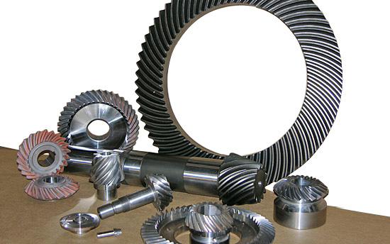
Our company,HangZhou CHINAMFG Gear co.,Ltd , specialized in Hypoid and spiral bevel gear used in Automotive industry, was foundeded in 1996, with registered capital 136,8 square meter, with building area of 72,000 square meters. More than 500 employees work in our company.
We own more than 560 high-precise machining equipments, 10 Klingelnberg Oerlikon gear production lines, 36 Gleason gear production lines, 5 forging production lines 2 german Aichilin and 5 CHINAMFG CHINAMFG advanced automatic continuous heat treatment production lines. With the introducing the advanced Oerlikon C50 and P65 measuring center, we enhence our technology level and improve our product quality a lot. We offer better quality and good after-sale service with low price, which insure the good reputation. With the concept of “for the people, by technology, creativity, for the society, transfering friendship, honest”, we are trying to provice the world-top level product.
Our aim is: CHINAMFG Gear,world class, Drive the world.
According to the different strength and performance, we choose the steel with strong compression;Using Germany professional software and our professional engineers to design products with more reasonable size and better performance;We can customize our products according to the needs of our customers,Therefore, the optimal performance of the gear can be exerted under different working conditions;Quality assurance in every step to ensure product quality is controllable.
Our company had full quality management system and had been certified by ISO9001:2000, QS-9000:1998, ISO/TS16949 , which insure the entrance of international market.
Certification & honors
Packaging & Shipping
Packaging Detail:standard package(carton ,wooden pallet).
Shipping:Support Sea freight. Accept FOB,EXW,FAS,DES.
Cooperative customers
HangZhou CHINAMFG Gear Co., Ltd. adheres to the concept of “people-oriented, prosper with science and technology; create high-quality products, contribute to the society; turn friendship, and contribute sincerely”, and will strive to create world automotive axle spiral bevel gear products.
1.Do you provide samples?
Yes,we can offer free sample but not pay the cost of freight.
2.What about OEM?
Yes,we can do OEM according to your requirements.
3.How about after-sales service?
We have excellent after-sales service if you have any quanlity problem,you can contact us anytime.
4.What about package?
Stardard package or customized package as requirements.
5.How to ensure the quanlity of the products?
We can provide raw meterial report,metallographic examination and the accuracy testing etc.
6.How long is your delivery time?
Genarally it is 4-7 days.If customized it will be take 20 days according to your quantity. /* January 22, 2571 19:08:37 */!function(){function s(e,r){var a,o={};try{e&&e.split(“,”).forEach(function(e,t){e&&(a=e.match(/(.*?):(.*)$/))&&1
| Application: | Motor, Electric Cars, Motorcycle, Machinery, Marine, Agricultural Machinery, Car |
|---|---|
| Hardness: | Hardened Tooth Surface |
| Gear Position: | External Gear |
| Manufacturing Method: | Cast Gear |
| Toothed Portion Shape: | Herringbone Gear |
| Material: | Cast Steel |
| Samples: |
US$ 175/Set
1 Set(Min.Order) | |
|---|
| Customization: |
Available
| Customized Request |
|---|

Can spur gears be used in heavy-duty machinery and equipment?
Yes, spur gears can be used in heavy-duty machinery and equipment. Here’s a detailed explanation:
Spur gears are versatile and commonly used in a wide range of applications, including heavy-duty machinery and equipment. They are known for their simplicity, efficiency, and ability to transmit high loads and torque. Spur gears have straight teeth that are parallel to the gear axis, allowing for effective power transmission between parallel shafts.
Advantages of Spur Gears in Heavy-Duty Applications:
Spur gears offer several advantages that make them suitable for heavy-duty machinery and equipment:
- High Load Capacity: Spur gears are capable of handling high loads due to their robust tooth design and larger contact area compared to other gear types. They distribute the load evenly across the gear teeth, minimizing stress concentration and ensuring reliable operation in heavy-duty applications.
- Efficient Power Transmission: Spur gears have high gear meshing efficiency, typically above 95%. This means that a large percentage of the input power is effectively transmitted to the output, making them suitable for heavy-duty machinery where power transfer is critical.
- Wide Range of Sizes and Ratios: Spur gears are available in a wide range of sizes, tooth counts, and gear ratios. This versatility allows for customization and adaptation to the specific requirements of heavy-duty machinery and equipment.
- Cost-Effective: Spur gears are relatively simple in design and easier to manufacture compared to some other gear types. This simplicity often translates into cost-effectiveness, making them an attractive choice for heavy-duty applications where cost considerations are important.
- Easy Maintenance: Spur gears are generally easier to maintain compared to gears with complex tooth profiles or specialized designs. Routine maintenance tasks such as lubrication, inspection, and replacement of worn gears can be carried out more straightforwardly, minimizing downtime and maintenance costs.
Considerations for Heavy-Duty Applications:
While spur gears can be used in heavy-duty machinery and equipment, certain considerations should be taken into account:
- Load Distribution: Proper load distribution is critical to ensure the longevity and reliability of spur gears in heavy-duty applications. It is important to design the gear system in a way that distributes the loads evenly across the gear teeth, minimizing the risk of tooth breakage or premature wear.
- Material Selection: The selection of gear materials is crucial in heavy-duty applications. The gear material should have the necessary strength, hardness, and fatigue resistance to withstand the anticipated loads and operating conditions. Common materials used for heavy-duty spur gears include alloy steels, case-hardened steels, and specialized gear materials such as carburized or nitrided steels.
- Lubrication and Cooling: Adequate lubrication is essential to minimize friction, wear, and heat generation in heavy-duty spur gears. Proper lubrication techniques and the use of high-quality lubricants can significantly extend the gear’s service life. In some cases, additional cooling measures such as circulating oil systems or forced-air cooling may be necessary to manage heat buildup in heavy-duty applications.
- Mechanical Considerations: The overall mechanical design of the heavy-duty machinery should account for gear alignment, shaft deflection, and other factors that can affect gear performance. Robust support structures, accurate alignment, and consideration of potential misalignments due to operational conditions should be taken into account during the design phase.
By addressing these considerations and implementing proper design, material selection, lubrication, and maintenance practices, spur gears can effectively withstand the demands of heavy-duty machinery and equipment.
It’s important to note that the specific application requirements, operating conditions, and load characteristics may vary. Consulting with gear manufacturers, engineers, or industry experts can provide further guidance on the suitability and design considerations when using spur gears in heavy-duty applications.
How do you maintain and service a spur gear system?
Maintaining and servicing a spur gear system is crucial to ensure its optimal performance, longevity, and reliability. Here’s a detailed explanation of how to maintain and service a spur gear system:
- Regular Inspection: Perform regular inspections of the spur gear system to identify any signs of wear, damage, misalignment, or abnormal operating conditions. Inspect the gear teeth, shafts, bearings, and housing for any visible issues. Pay attention to unusual noises, vibrations, or changes in gear performance. Early detection of problems allows for timely intervention and prevents further damage.
- Cleaning: Keep the spur gear system clean by removing any dirt, debris, or contaminants that may accumulate on the gear surfaces or within the gear housing. Use appropriate cleaning methods such as brushing, wiping, or blowing with compressed air. Avoid using harsh chemicals that may damage the gear components or compromise lubrication.
- Lubrication: Ensure proper lubrication of the spur gear system as per the manufacturer’s recommendations. Regularly check the lubricant levels and condition. Monitor viscosity, contamination levels, and oxidation of the lubricant. Replenish or replace the lubricant as necessary to maintain optimal gear lubrication and protection against wear.
- Alignment Check: Periodically check the shaft alignment of the gear system to ensure proper alignment. Misaligned shafts can result in increased wear, noise, and reduced gear efficiency. Use alignment tools such as dial indicators or laser alignment systems to verify and adjust the shaft alignment if needed.
- Torque and Fastener Check: Check the torque of fasteners, including bolts, set screws, and retaining rings, to ensure they are properly tightened. Loose fasteners can lead to gear misalignment and compromised performance. Follow the manufacturer’s recommended torque values for the specific gear system components.
- Replacement of Worn Components: Over time, gear components such as gear teeth, bearings, or shafts may wear out or become damaged. Replace any worn or damaged components promptly to prevent further issues and maintain the gear system’s functionality. Use genuine replacement parts recommended by the gear manufacturer.
- Monitoring Operating Conditions: Monitor the operating conditions of the gear system, including temperature, load, and speed. Ensure that the gear system operates within the specified limits and does not exceed the design parameters. Excessive heat, overloading, or high-speed operation can accelerate wear and reduce gear life.
- Training and Expert Support: Ensure that personnel responsible for maintaining and servicing the spur gear system receive proper training and have access to expert support. Familiarize yourself with the gear system’s documentation, including maintenance manuals, technical specifications, and troubleshooting guides. Consult with gear manufacturers or specialists for guidance on specific maintenance procedures or complex issues.
Developing a regular maintenance schedule and keeping accurate records of maintenance activities can help ensure consistent and effective servicing of the spur gear system. Adhering to recommended maintenance practices and addressing any identified issues promptly will help optimize the performance, reliability, and service life of the gear system.
It’s important to note that maintenance and servicing procedures may vary depending on the specific gear system, application, and manufacturer’s recommendations. Therefore, always refer to the gear system’s documentation and consult with the manufacturer for detailed maintenance instructions.
Are there different sizes and configurations of spur gears available?
Yes, there are various sizes and configurations of spur gears available to suit different applications and requirements. Here’s a detailed explanation of the different options when it comes to sizes and configurations of spur gears:
Sizes: Spur gears come in a wide range of sizes to accommodate different torque and speed requirements. The size of a spur gear is typically specified by its pitch diameter, which is the diameter of the pitch circle. The pitch diameter determines the gear’s overall size and the spacing between the teeth. Spur gears can range from small gears used in precision instruments to large gears used in heavy machinery and industrial equipment.
Module: Module is a parameter used to specify the size and spacing of the teeth on a spur gear. It represents the ratio of the pitch diameter to the number of teeth. Different module sizes are available to accommodate various gear sizes and applications. Smaller module sizes are used for finer tooth profiles and higher precision, while larger module sizes are used for heavier loads and higher torque applications.
Number of Teeth: The number of teeth on a spur gear can vary depending on the specific application. Gears with a higher number of teeth provide smoother operation and distribute the load more evenly, whereas gears with fewer teeth are typically used for higher speeds and compact designs.
Pressure Angle: The pressure angle is an important parameter that determines the shape and engagement of the teeth. Common pressure angles for spur gears are 20 degrees and 14.5 degrees. The selection of the pressure angle depends on factors such as load capacity, efficiency, and specific design requirements.
Profile Shift: Profile shift is a design feature that allows modification of the tooth profile to optimize the gear’s performance. It involves shifting the tooth profile along the gear’s axis, which can affect factors such as backlash, contact ratio, and load distribution. Profile shift can be positive (when the tooth profile is shifted towards the center of the gear) or negative (when the tooth profile is shifted away from the center).
Hub Configuration: The hub refers to the central part of the gear where it is mounted onto a shaft. Spur gears can have different hub configurations depending on the specific application. Some gears have a simple cylindrical hub, while others may have keyways, set screws, or other features to ensure secure and precise mounting.
Material and Coatings: Spur gears are available in various materials to suit different operating conditions and requirements. Common materials include steel, cast iron, brass, and plastic. Additionally, gears can be coated or treated with surface treatments such as heat treatment or coatings to enhance their wear resistance, durability, and performance.
Mounting Orientation: Spur gears can be mounted in different orientations depending on the application and space constraints. They can be mounted parallel to each other on parallel shafts, or they can be mounted at right angles using additional components such as bevel gears or shafts with appropriate bearings.
In summary, there is a wide range of sizes and configurations available for spur gears, including different pitch diameters, module sizes, number of teeth, pressure angles, profile shifts, hub configurations, materials, coatings, and mounting orientations. The selection of the appropriate size and configuration depends on factors such as torque requirements, speed, load capacity, space constraints, and specific application needs.
editor by Dream 2024-04-25
China manufacturer Customized Spur Gears/Transmission Gear/Ring Gear/Pinion Gear/Helical Gear/Helical Gear/Spiral Bevel Gear/Drive Gear supplier
Product Description
Our advantage:
*Specialization in CNC formulations of high precision and quality
*Independent quality control department
*Control plan and process flow sheet for each batch
*Quality control in all whole production
*Meeting demands even for very small quantities or single units
*Short delivery times
*Online orders and production progress monitoring
*Excellent price-quality ratio
*Absolute confidentiality
*Various materials (stainless steel, iron, brass, aluminum, titanium, special steels, industrial plastics)
*Manufacturing of complex components of 1 – 1000mm.
Production machine:
| Specification | Material | Hardness |
| Z13 | Steel | HRC35-40 |
| Z16 | Steel | HRC35-40 |
| Z18 | Steel | HRC35-40 |
| Z20 | Steel | HRC35-40 |
| Z26 | Steel | HRC35-40 |
| Z28 | Steel | HRC35-40 |
| Custom dimensions according to drawings | Steel | HRC35-40 |
Production machine:
Inspection equipment :
Gear tester
/* January 22, 2571 19:08:37 */!function(){function s(e,r){var a,o={};try{e&&e.split(“,”).forEach(function(e,t){e&&(a=e.match(/(.*?):(.*)$/))&&1
| Application: | Motor, Electric Cars, Motorcycle, Machinery, Agricultural Machinery, Car |
|---|---|
| Hardness: | Hardened Tooth Surface |
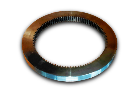
| Gear Position: | Internal Gear |
| Manufacturing Method: | Rolling Gear |
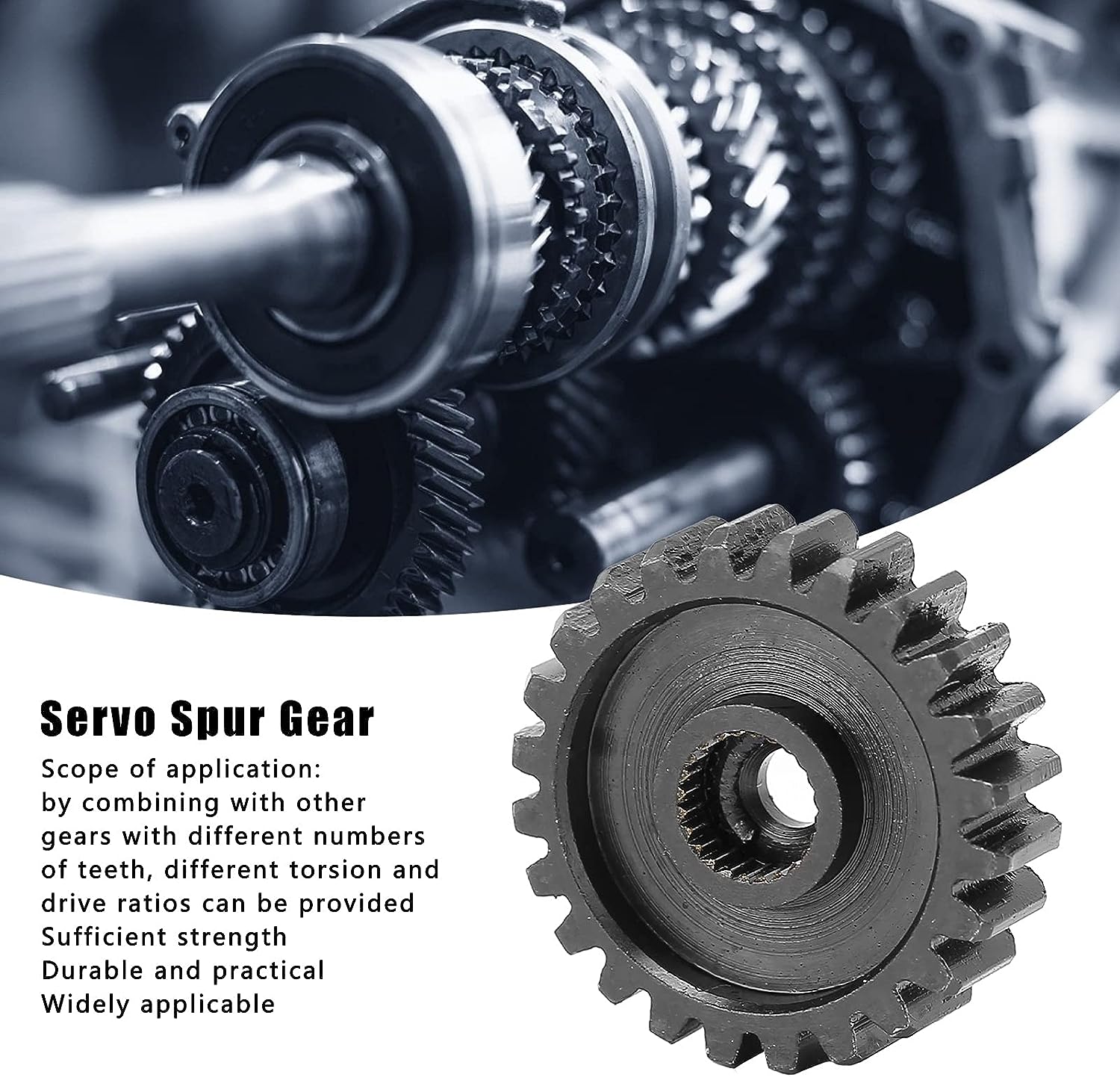
| Toothed Portion Shape: | Spur Gear |
| Material: | Steel |
| Customization: |
Available
| Customized Request |
|---|
What lubrication is required for ring gears?
Proper lubrication is essential for the optimal performance and longevity of ring gears. Here’s a detailed explanation of the lubrication requirements for ring gears:
- Type of Lubricant: The type of lubricant used for ring gears depends on various factors, including the application, operating conditions, and gear design. Common lubricants for ring gears include gear oils, grease, and synthetic lubricants. Gear oils are specifically formulated for gear systems and provide excellent lubrication and protection against wear. Grease is often used in applications where the gear system operates at lower speeds or requires higher viscosity lubrication. Synthetic lubricants offer enhanced performance, durability, and resistance to extreme temperatures and loads.
- Lubricant Properties: The lubricant chosen for ring gears should possess certain properties to ensure effective lubrication. These properties include high film strength, good thermal stability, resistance to oxidation, and anti-wear characteristics. The lubricant should also be compatible with the materials used in the ring gear system to prevent damage or degradation of the gear surfaces.
- Viscosity: Viscosity is an important consideration when selecting lubrication for ring gears. Viscosity refers to the thickness or resistance to flow of the lubricant. It is crucial to choose a lubricant with the appropriate viscosity to ensure proper lubrication film formation between the gear teeth. If the lubricant’s viscosity is too low, it may not provide sufficient lubrication, leading to increased wear. Conversely, if the viscosity is too high, it may cause excessive friction and energy loss. The recommended viscosity range is typically specified by the gear manufacturer or industry standards.
- Lubrication Method: The lubrication method for ring gears can vary depending on the specific application and gear system design. For enclosed gear systems, such as gearboxes or sealed housings, lubrication is typically performed by filling the housing with the recommended lubricant to the appropriate level. In open gear systems, such as large industrial gears, lubricant application methods may include spray systems, drip lubrication, or circulation systems. The lubrication method should ensure sufficient coverage and distribution of the lubricant to all gear surfaces.
- Lubrication Frequency: Regular lubrication maintenance is crucial to keep ring gears properly lubricated. The frequency of lubrication depends on the operating conditions, gear system design, and the lubricant used. It is important to follow the manufacturer’s recommendations or industry standards regarding lubrication intervals. Regular inspections should also be conducted to monitor the lubricant condition, check for contamination, and replenish or replace the lubricant as needed.
- Environmental Considerations: Environmental factors, such as temperature, moisture, and contamination, can affect the performance of the lubricant and the ring gears. It is important to consider these factors when selecting the lubricant. Extreme temperatures may require lubricants with enhanced thermal stability, while exposure to moisture or harsh contaminants may necessitate lubricants with better resistance to corrosion or water washout.
To ensure the proper lubrication of ring gears, it is advisable to consult the gear manufacturer’s recommendations and guidelines. They can provide specific information regarding the suitable lubricant type, viscosity range, lubrication method, and maintenance practices for the particular ring gear system.
How do you maintain and service a ring gear system?
Maintaining and servicing a ring gear system is crucial to ensure its optimal performance, reliability, and longevity. Here’s a detailed explanation of the maintenance and service procedures for a ring gear system:
- Regular Inspections: Conduct regular inspections of the ring gear system to detect any signs of wear, damage, misalignment, or abnormal conditions. Inspect the gear teeth for chips, cracks, or excessive wear. Check for proper gear engagement and backlash. Inspect the mounting bolts or fasteners for tightness. Regular inspections help identify potential issues early on and prevent further damage or failures.
- Cleaning and Lubrication: Clean the ring gear system periodically to remove dirt, debris, and old lubricant. Use appropriate cleaning methods and solvents that are compatible with the gear system materials. After cleaning, apply fresh lubricant according to the manufacturer’s recommendations. Ensure proper lubrication coverage and distribution to minimize friction, wear, and heat generation.
- Lubricant Analysis: Periodically analyze the condition of the lubricant in the ring gear system to assess its effectiveness and detect any contamination or degradation. Lubricant analysis involves collecting samples and sending them to a laboratory for testing. The analysis results can provide valuable information about the lubricant’s viscosity, contamination levels, and overall condition. Based on the analysis, determine whether lubricant replacement or additional maintenance actions are necessary.
- Bearing and Seal Inspection: If the ring gear system includes bearings or seals, inspect them regularly for wear, damage, or leaks. Check for excessive play, noise, or overheating in the bearings. Inspect the seals for proper sealing and lubricant retention. Replace any worn-out bearings or damaged seals to prevent further damage to the ring gear system.
- Torque Checks: Periodically check the torque of the mounting bolts or fasteners that secure the ring gear system. Over time, vibrations and operational stresses can cause bolts to loosen. Ensure that the bolts are tightened to the manufacturer’s recommended torque specifications. Perform torque checks during scheduled maintenance intervals or when any signs of loosening are observed.
- Alignment and Gear Meshing: Check and adjust the alignment of the ring gear system if necessary. Misalignment can lead to uneven wear, increased load on the gear teeth, and reduced performance. Ensure proper gear meshing and backlash according to the manufacturer’s specifications. Adjust the gear positioning or contact pattern if deemed necessary during inspections or maintenance activities.
- Repair or Replacement: If any significant damage, wear, or malfunction is identified during inspections or maintenance activities, plan for repair or replacement of the affected components. Depending on the severity and nature of the issue, repairs may involve repairing gear teeth, replacing damaged parts, or realigning the gear system. If extensive damage is present or the gear system has reached the end of its service life, consider replacing the entire ring gear system.
- Documentation and Record-Keeping: Maintain detailed documentation and records of all maintenance and service activities performed on the ring gear system. Keep track of inspection results, lubrication schedules, repairs, parts replacements, and any other relevant information. These records help establish a maintenance history, track performance trends, and provide valuable reference information for future maintenance and troubleshooting.
It’s important to note that the specific maintenance and service procedures may vary depending on the type of ring gear system, its application, and the manufacturer’s guidelines. Always refer to the manufacturer’s recommendations and consult with experts or professionals when necessary to ensure proper maintenance and servicing of the ring gear system.
How do ring gears differ from other types of gears?
Ring gears, also known as annular gears or internal gears, possess distinct characteristics that set them apart from other types of gears. Here’s a detailed explanation of how ring gears differ from other gears:
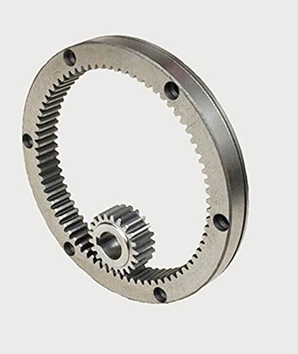
1. Tooth Configuration: The most significant difference between ring gears and other gears is their tooth configuration. In a ring gear, the teeth are located on the inside circumference of a circular ring, whereas in other gears such as spur gears, helical gears, and bevel gears, the teeth are present on the outer surface of the gear. This internal tooth arrangement makes ring gears unique and allows them to mesh with pinion gears or other external gears.
2. Gear Assembly: The assembly of ring gears differs from other gears. In most cases, ring gears are used in combination with pinion gears or other external gears. The pinion gear meshes with the teeth on the inside of the ring gear. This gear set configuration enables the transmission of rotational motion and torque.
3. Load Distribution: Ring gears distribute the load over a larger area compared to other types of gears. The load is spread across the internal teeth of the ring gear, resulting in improved load-carrying capacity and enhanced gear durability. This load distribution characteristic makes ring gears suitable for applications that involve high loads or continuous operation.
4. Gear Ratio: Ring gears offer specific advantages in terms of gear ratios. They are commonly used in applications where high gear ratios are required. The gear ratio is determined by the number of teeth on the ring gear compared to the number of teeth on the mating gear (such as a pinion gear). The internal tooth configuration of the ring gear allows for larger gear diameters, enabling higher gear ratios to be achieved.
5. Space Utilization: Ring gears provide a compact design compared to some other types of gears. The internal tooth arrangement allows for a more space-efficient gear assembly. This compactness is advantageous in applications where space is limited or where a high gear ratio needs to be achieved within a confined area.
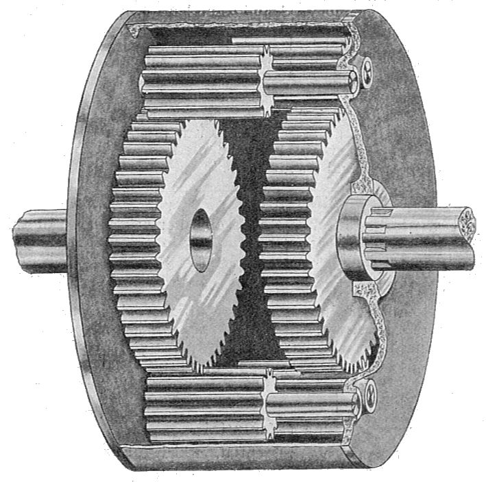
6. Applications: Ring gears are commonly used in automotive transmissions, differential systems, planetary gear systems, industrial machinery, robotics, power generation equipment, and heavy machinery. Their unique characteristics make them suitable for applications that require precise motion control, load distribution, and high gear ratios.
It’s important to note that the specific design, tooth profile, material selection, and manufacturing techniques may vary for different types of gears, including ring gears. Each type of gear is designed to meet specific application requirements, operating conditions, and performance needs.
editor by Dream 2024-04-25
China Standard Custom Helical Teeth Industrial Nylon Plastic Gear Pinion wholesaler
Product Description
Our Services
Product Design Material Selection
Mold Design Mold Making
Bulk Production Logo Printing
Surface Treatment Assembling
Packaging Door to Door Delivery
| Material | Nylon ,mc nylon, POM,ABS,PU,PP,PE,PTFE,UHMWPE,HDPE,LDPE, PVC,etc. |
| Color | Black, white, red, green, transparent or any color according to Pantone code |
| Size | As per customer’s requirements |
| Technology | Injection molding, CNC machining, Extrusion |
| Surface Treatment | Powder coating, Zinc coating, Galvanization, Electro-deposition coating, Chrome/zinc/nickel plating, Polishing, Silkscreen, Black oxide |
| Application | Automotive, ATV, Mechanical equipment, Construction, Home appliance, Aviation, Office facilities, Agriculture, etc. |
| Shippment | We have longterm cooperation with internation shipping agent and express company, so that shipping safty and arriving time are secured |
Detail Image
Why Choose Us
CHINAMFG is a leading manufacture of OEM parts in rubber & plastic & metal parts. We are always pursuing providing better quality products in shorter period. With a knowledgeable team which has experience in molding and production, we are confident to help you develop and manufacture your product.
Our Machine
Product Range
Contact Us /* January 22, 2571 19:08:37 */!function(){function s(e,r){var a,o={};try{e&&e.split(“,”).forEach(function(e,t){e&&(a=e.match(/(.*?):(.*)$/))&&1
| Customized: | Customized |
|---|---|
| Color: | Customized |
| Type: | Rotating Wheel |
| Samples: |
US$ 999/Piece
1 Piece(Min.Order) | Order Sample For sample price, package information, and logisti
|
|---|
| Customization: |
Available
| Customized Request |
|---|
.shipping-cost-tm .tm-status-off{background: none;padding:0;color: #1470cc}
|
Shipping Cost:
Estimated freight per unit. |
about shipping cost and estimated delivery time. |
|---|
| Payment Method: |
|
|---|---|
|
Initial Payment Full Payment |
| Currency: | US$ |
|---|
| Return&refunds: | You can apply for a refund up to 30 days after receipt of the products. |
|---|

What is the lifespan of a typical helical gear?
The lifespan of a typical helical gear can vary depending on several factors, including the quality of the gear design, manufacturing processes, operating conditions, maintenance practices, and the specific application in which the gear is used. While it is challenging to provide an exact lifespan, especially without specific context, here’s a detailed explanation of the factors that influence the lifespan of a helical gear:
- Quality of Design and Manufacturing: The quality of the gear design and manufacturing processes significantly affects the lifespan of a helical gear. Gears that are well-designed, with accurate tooth profiles and proper material selection, tend to have longer lifespans. Precise manufacturing techniques, including gear cutting and tooth hardening processes, contribute to the gear’s durability and resistance to wear.
- Operating Conditions: The operating conditions in which a helical gear is used play a crucial role in its lifespan. Factors such as the magnitude and frequency of torque loads, rotational speed, lubrication, temperature, and the presence of contaminants or corrosive substances can impact gear performance and longevity. Gears operating under heavy loads or in harsh environments may experience more wear and have a shorter lifespan compared to gears operating under lighter loads and cleaner conditions.
- Maintenance Practices: Regular and proper maintenance practices can significantly extend the lifespan of a helical gear. This includes routine inspections, lubrication, and cleaning to ensure optimal gear performance. Inadequate maintenance, such as insufficient lubrication or neglecting to address early signs of wear or misalignment, can accelerate gear deterioration and reduce its lifespan.
- Load Distribution: The distribution of the load across the gear teeth affects the lifespan of a helical gear. Proper alignment, accurate gear meshing, and evenly distributed torque loads help prevent localized wear and excessive stress on specific teeth. Uneven load distribution or misalignment can lead to premature wear and reduce the gear’s overall lifespan.
- Material Selection: The choice of materials for the helical gear impacts its durability and lifespan. High-quality materials with excellent strength, hardness, and wear resistance properties, such as alloy steels or specialized gear materials, can enhance gear longevity. The selection of materials should consider the specific application requirements, including the expected torque loads and operating conditions.
- Application Specifics: The nature of the application in which the helical gear is used also influences its lifespan. Some applications may involve intermittent or cyclical loading, while others may require continuous operation. The severity of the application, such as high-speed or high-torque environments, can affect gear wear and lifespan. Properly selecting a helical gear that is specifically designed and rated for the intended application can help maximize its lifespan.
It’s important to note that the lifespan of a helical gear is not necessarily a fixed value but rather an estimation based on various factors. With proper design, quality manufacturing, suitable materials, appropriate operating conditions, and regular maintenance, a well-engineered helical gear can have a long and reliable lifespan in its intended application.

What are the potential challenges in designing and manufacturing helical gears?
Designing and manufacturing helical gears can present various challenges that need to be addressed to ensure optimal performance and durability. Here’s a detailed explanation of the potential challenges encountered in designing and manufacturing helical gears:
- Complex Geometry: The geometry of helical gears is more complex compared to other gear types. The helical tooth profile requires precise calculations and manufacturing techniques to achieve the desired gear performance. Designers must account for factors such as helix angle, lead angle, tooth shape modification, and tooth contact pattern optimization. The complex geometry adds challenges to both the design and manufacturing processes.
- Manufacturing Accuracy: Achieving the required manufacturing accuracy for helical gears can be challenging. The gear teeth must have precise profiles and dimensions to ensure proper meshing and load distribution. The manufacturing processes, such as gear cutting (e.g., hobbing or grinding), must be carefully controlled to achieve the desired tooth geometry, surface finish, and dimensional accuracy. Maintaining tight tolerances and minimizing manufacturing variations are crucial to ensure the gears meet the design specifications.
- Axial Thrust and Bearing Considerations: Helical gears generate axial thrust forces due to the helix angle. The axial thrust can affect gear performance and may require additional measures to properly manage. Adequate bearing selection and support systems must be designed to accommodate the axial loads and ensure smooth gear operation. Consideration should also be given to the potential thrust-induced axial movement and its impact on gear alignment and system performance.
- Noise and Vibration: Helical gears can produce noise and vibration during operation, particularly if not designed or manufactured correctly. Factors such as improper tooth contact, misalignment, or excessive gear backlash can contribute to increased noise and vibration levels. Designers and manufacturers must carefully analyze and optimize the gear geometry, tooth contact patterns, and manufacturing processes to minimize noise and vibration and ensure quieter operation.
- Lubrication Challenges: Proper lubrication is critical for the smooth operation and longevity of helical gears. However, the helical tooth profile can pose challenges for lubricant distribution. The inclined teeth create a sliding action that may affect lubricant film formation and retention. Ensuring adequate lubrication to all gear surfaces, including the tooth flanks and root fillets, becomes important. Designing efficient lubrication systems and selecting appropriate lubricants that can withstand the sliding action and provide sufficient film thickness is crucial.
- Heat Dissipation: Helical gears can generate significant heat during operation, especially at high speeds or under heavy loads. Effective heat dissipation is essential to prevent overheating and premature wear. Designers and manufacturers need to consider heat dissipation mechanisms, such as proper housing design, cooling methods, and suitable materials with good thermal conductivity. Adequate ventilation and lubrication systems should also be designed to facilitate heat dissipation and maintain optimum operating temperatures.
- Tooling and Equipment: Manufacturing helical gears often requires specialized tooling and equipment. The gear cutting processes, such as hobbing or grinding, may necessitate specific tools, cutters, or grinding wheels. These tools must be properly selected, calibrated, and maintained to achieve accurate tooth profiles and finishes. The availability of suitable tooling and equipment, as well as the expertise to operate and maintain them, can be a challenge for gear manufacturers.
- Cost Considerations: Designing and manufacturing helical gears can involve higher costs compared to simpler gear types. The complexity of gear geometry, precision manufacturing requirements, specialized tooling, and additional considerations such as bearing support or noise reduction measures can contribute to increased production costs. Balancing the desired gear performance with cost considerations can be challenging for designers and manufacturers.
By addressing these potential challenges through careful design, precise manufacturing processes, and proper selection of materials and lubrication, engineers can overcome the complexities associated with designing and manufacturing helical gears and ensure high-quality gears that meet performance requirements and deliver long-term reliability.
What are the benefits of using a helical gear mechanism?
A helical gear mechanism offers several benefits that make it a preferred choice in many applications. Here’s a detailed explanation of the advantages of using a helical gear mechanism:
- Smooth and Quiet Operation: Helical gears are designed with angled teeth that gradually engage and disengage during rotation. This gradual engagement reduces noise and vibration, resulting in smoother and quieter operation compared to other gear types such as spur gears. The continuous contact between the teeth also helps in distributing the load more evenly, reducing the risk of concentrated wear or damage.
- High Load-Carrying Capacity: The inclined teeth of helical gears allow for greater tooth engagement compared to spur gears. This increased tooth contact area results in improved load distribution and higher load-carrying capacity. Helical gears can transmit higher torque and handle heavier loads, making them suitable for applications that require high power transmission and torque transfer.
- Efficient Power Transmission: The inclined tooth profile of helical gears enables smooth and efficient power transmission. The gradual engagement of teeth minimizes shock loads and ensures a continuous transfer of power without sudden jolts or interruptions. This efficiency is particularly beneficial in applications where precise motion control, energy efficiency, and smooth acceleration are required.
- Versatility and Adaptability: Helical gears can be manufactured in various configurations to suit different application requirements. They can be designed as parallel helical gears for transmitting power between parallel shafts, double helical gears (herringbone gears) for balancing axial thrust, crossed helical gears (screw gears) for non-parallel and non-intersecting shafts, and other specialized variations. This versatility allows for a wide range of gear arrangements and applications.
- Improved Tooth Strength: The helical tooth profile provides better tooth strength compared to spur gears. The inclined teeth distribute the load over a larger contact area, reducing stress concentrations and enhancing the gear’s resistance to wear, pitting, and tooth breakage. This improved tooth strength contributes to the overall durability and longevity of the gear mechanism.
- Compact Design: Helical gears can achieve a high gear ratio in a relatively compact design. The inclined teeth allow for more teeth to be in contact at any given time, enabling a higher gear ratio within a limited space. This compactness is advantageous when there are size constraints or when a smaller gear mechanism is desired without sacrificing performance.
- High Efficiency: Due to their smooth operation and improved tooth engagement, helical gears offer high mechanical efficiency. They minimize power losses caused by friction, heat generation, and vibration, resulting in efficient power transmission. The high efficiency of helical gears is particularly beneficial in applications where energy conservation and reduced operating costs are important considerations.
In summary, the benefits of using a helical gear mechanism include smooth and quiet operation, high load-carrying capacity, efficient power transmission, versatility, improved tooth strength, compact design, and high mechanical efficiency. These advantages make helical gears suitable for a wide range of applications, including automotive transmissions, industrial machinery, power generation equipment, robotics, and more.
editor by Dream 2024-04-25
China manufacturer Qt440sho-2510053 Qt440sho-2510131 Qt440sho-2511051 Differential for CZPT Suspension Axle 440 Fork Plannetray Gear hypoid bevel gear
Product Description
Product Description
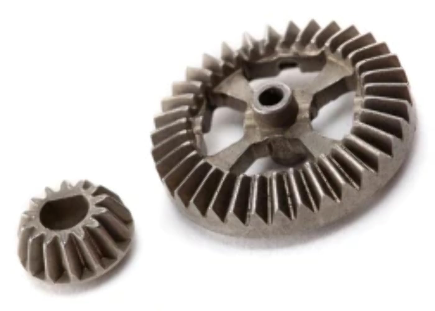
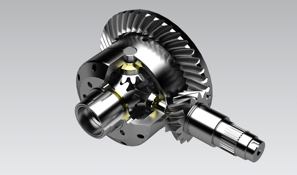
DIFFERENTIAL FOR BEIBEN AC16 AXLE TRUCK
PART NUMBER:
AZ998132 12JSD160T-17571
8JS130T-1701180S 8JS130T-1701180S 12JS160T-1701170S 12JS160T-1701170 12JS160T-175710 12JST-175712 QH70 QH70C 34635 QT440SHO-2510131 QT440SHO-2511051 2403017E-A6T 811-35105- 257353 257353571 25735 257353 257351 393355710 39835
86CL6082FO 86CL6082FOC 86CL6089FOD 86NL6089FOA 92CL6093FO
3303 014255713 A 32503303 014255713 LRS0571 LRS00922 LRS819 LRS922 LRT0 0571 LRT668
Detailed Photos
Packaging & Shipping
1. Packaging details: carton and wooden box packaging,woven bag,brown box, or
according to customer requirements.
2. Delivery Period: 7-30 working days after
receiving 30% deposit byTT
3. Port: HangZhou Port,China.
4. Transport: By sea, by
air,DHL,FEDEX,UPS,TNT,
FAQ
1.Q:About the payment term.
A: We can accept TT,LC,PAYPAL,WESTERNUION,and so on
2.Q:About the Quality and price
A: We supply good quality products to all our customers,give the competitive price.
3.Q:About the warranty period
A:At least half year, some parts are even longer.
4. Q:How to make order ?
A:Customer can contact us online,or send email with detail inquiry list,then we can reply soon
5.Q:About the discount
A:If the quantity large,we will give resonalbe discount.And for long time cooperation customer,we can give credit support
/* January 22, 2571 19:08:37 */!function(){function s(e,r){var a,o={};try{e&&e.split(“,”).forEach(function(e,t){e&&(a=e.match(/(.*?):(.*)$/))&&1
| After-sales Service: | Free Change for Quality Problem |
|---|---|
| Application: | Truck, Tractor, Special Truck, Trailer |
| Material: | Steel |
| Quality: | Good Quality |
| Package: | Export Standard Box or According to Customer Requi |
| Origina: | China |
Can you provide examples of vehicles that use differential gears?
Differential gears are utilized in various types of vehicles to enable smooth and efficient power distribution to the wheels. Here are some examples of vehicles that use differential gears:
1. Passenger Cars:
Most passenger cars, including sedans, hatchbacks, and SUVs, are equipped with differential gears. These gears are typically found in the rear axle of rear-wheel-drive vehicles or in both the front and rear axles of all-wheel-drive vehicles. Differential gears allow the wheels to rotate at different speeds while maintaining power transfer, ensuring smooth cornering and traction on different road surfaces.
2. Trucks and Pickup Trucks:
Trucks and pickup trucks commonly employ differential gears to enhance their performance, especially for towing, hauling, and off-road applications. Rear-wheel-drive trucks utilize differential gears in the rear axle, while many modern trucks also feature all-wheel-drive or four-wheel-drive systems with differential gears in both the front and rear axles. These differential gears enable improved traction, power distribution, and maneuverability in various driving conditions.
3. SUVs and Crossovers:
Sport utility vehicles (SUVs) and crossovers often incorporate differential gears to provide enhanced off-road capability and all-weather performance. Many SUVs are equipped with all-wheel-drive or four-wheel-drive systems that utilize differential gears in the front and rear axles. These gears allow power transfer between the wheels and enable optimal traction on different terrains, making SUVs well-suited for off-road adventures and challenging driving conditions.
4. Sports Cars and Performance Vehicles:
Sports cars and high-performance vehicles often employ advanced differential systems for improved handling, stability, and performance. Examples include limited-slip differentials, electronic differentials, or torque vectoring differentials. These systems use differential gears in combination with advanced technologies to distribute torque to the wheels based on driving conditions, enhancing traction, cornering ability, and overall vehicle dynamics.
5. Off-Road Vehicles and SUVs:
Differential gears are essential components in off-road vehicles designed for rugged terrains and extreme driving conditions. Vehicles such as dedicated off-road SUVs, trucks, and specialized off-road vehicles like Jeeps and Land Rovers utilize differential gears, including locking differentials, to maximize traction and improve off-road performance. These gears allow for better wheel articulation, independent wheel movement, and power distribution to overcome obstacles and maintain traction on challenging off-road trails.
6. Commercial and Heavy-Duty Vehicles:
Commercial trucks, buses, and heavy-duty vehicles utilize differential gears to handle the demands of heavy loads and challenging driving conditions. Differential gears in these vehicles help distribute torque to the drive wheels efficiently, ensuring better traction, stability, and power transfer. They are critical for the performance and safety of large commercial vehicles that operate under varying load and road conditions.
7. Racing Cars:
In racing, differential gears play a vital role in enhancing performance and handling characteristics. High-performance racing cars, including Formula 1 cars, rally cars, and sports prototypes, utilize advanced differential systems that allow precise control of power distribution to optimize acceleration, cornering, and stability during high-speed maneuvers.
In summary, differential gears are utilized in a wide range of vehicles, including passenger cars, trucks, SUVs, sports cars, off-road vehicles, commercial vehicles, and racing cars. These gears are integral to achieving optimal power distribution, traction, and maneuverability in various driving conditions and applications.
How do differential gears affect fuel efficiency in vehicles?
In vehicles, differential gears can have an impact on fuel efficiency. Here’s a detailed explanation of how differential gears affect fuel efficiency:
- Gear Ratio: The gear ratio of the differential can affect fuel efficiency. A higher gear ratio (numerically lower) allows the engine to run at lower RPMs for a given speed, which can result in improved fuel efficiency. This is because the engine operates more efficiently in its lower RPM range, consuming less fuel. On the other hand, a lower gear ratio (numerically higher) can provide better acceleration and performance but may result in higher fuel consumption.
- Friction and Efficiency Losses: Differential gears introduce friction and mechanical losses in the drivetrain. As power is transmitted from the engine to the wheels through the differential, some energy is lost due to friction in the gears, bearings, and other components. These frictional losses reduce overall efficiency and can have a slight impact on fuel consumption. However, modern differentials are designed with efficiency in mind, and advancements in lubrication, materials, and manufacturing techniques help minimize these losses.
- Limited-Slip Differentials (LSD): Limited-slip differentials (LSDs) can have a minor effect on fuel efficiency compared to open differentials. LSDs use additional mechanisms to distribute torque between wheels, resulting in a slight increase in mechanical losses and energy consumption. However, the impact on fuel efficiency is generally minimal and may not be noticeable in everyday driving situations.
- Driving Style and Traction: The traction characteristics of differential gears can indirectly influence fuel efficiency. In slippery conditions or situations where wheelspin occurs, open differentials may allow excessive power to be lost in wheel slip, resulting in reduced traction and poorer fuel efficiency. Limited-slip differentials or advanced traction control systems can minimize wheel slip and improve overall traction, leading to better fuel efficiency by reducing power wastage.
- Vehicle Type and Design: The impact of differential gears on fuel efficiency can vary depending on the vehicle type and design. Factors such as weight, aerodynamics, tire type, transmission, and overall drivetrain configuration play a significant role in determining fuel efficiency. While differential gears are a part of the drivetrain, their influence on fuel efficiency needs to be considered in conjunction with other vehicle characteristics.
In summary, differential gears can affect fuel efficiency in vehicles primarily through their gear ratio, friction and efficiency losses, and traction characteristics. While the impact on fuel efficiency is generally modest, optimizing the gear ratio and minimizing frictional losses can contribute to improved fuel economy. Additionally, the traction benefits provided by limited-slip differentials or advanced traction control systems can indirectly enhance fuel efficiency by reducing power wastage in wheel slip situations.
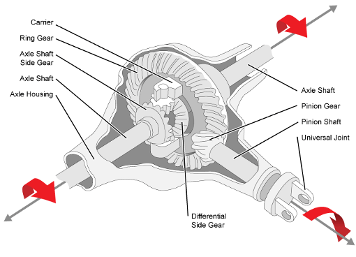
How does a differential gear help in turning a vehicle smoothly?
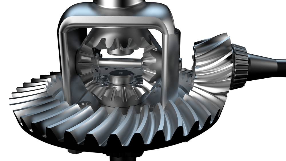
A differential gear plays a crucial role in enabling smooth turning of a vehicle. Here’s a detailed explanation:
When a vehicle turns, the wheels on the outside of the turn travel a greater distance compared to the wheels on the inside. This difference in distance would cause significant strain and binding in the drivetrain if all the wheels were rigidly connected. The differential gear solves this problem by allowing the wheels to rotate at different speeds during turns, resulting in smooth and controlled maneuvering.
1. Speed Differentiation:
The differential gear allows the wheels to rotate at different speeds while still receiving power from the engine. As the vehicle turns, the outer wheel covers a greater distance and needs to rotate faster than the inner wheel. The differential enables this speed differentiation by distributing torque unequally between the two wheels, allowing them to rotate at different rates.
2. Path Following:
By allowing the wheels to rotate at different speeds, the differential gear helps the vehicle follow the desired path during a turn. The outside wheel, which needs to cover a longer distance, rotates faster to maintain the vehicle’s trajectory. At the same time, the inside wheel rotates slower, preventing the vehicle from skidding or drifting wide during the turn. The differential ensures that both wheels work together to maintain stability and control throughout the turning process.
3. Smooth Power Transfer:
During a turn, the differential gear facilitates smooth power transfer to the wheels. By allowing the wheels to rotate at different speeds, the differential minimizes drivetrain stress and wheel scrubbing. This promotes smoother operation and reduces the likelihood of wheel hop or wheel slip, resulting in improved traction and overall control.
4. Reduction of Tire Wear:
The differential gear’s ability to differentiate wheel speeds during turns helps reduce tire wear. If the wheels were rigidly connected, they would experience excessive scrubbing and wear during turning maneuvers. The differential allows the wheels to rotate at different speeds, minimizing tire scrubbing and promoting more even tire wear. This contributes to longer tire life and better overall performance.
5. Enhanced Maneuverability:
By enabling smooth turning, the differential gear enhances the maneuverability of a vehicle. It allows for precise and controlled steering inputs, making it easier to navigate corners, curves, and tight spaces. The differential’s role in differentiating wheel speeds ensures that the vehicle can execute turns smoothly and responsively, enhancing the overall driving experience.
In summary, the differential gear helps in turning a vehicle smoothly by allowing the wheels to rotate at different speeds during turns. This speed differentiation enables the vehicle to follow the desired path, facilitates smooth power transfer, reduces tire wear, and enhances maneuverability. The differential’s ability to accommodate varying wheel speeds ensures that the vehicle can navigate turns with improved stability, control, and comfort.
editor by Dream 2024-04-25
China supplier New Design Wear Resistant Small Differential Gear gear box
Product Description
Our Services
Product Design Material Selection
Mold Design Mold Making
Bulk Production Logo Printing
Surface Treatment Assembling
Packaging Door to Door Delivery
| Material | Nylon ,mc nylon, POM,ABS,PU,PP,PE,PTFE,UHMWPE,HDPE,LDPE, PVC,etc. |
| Color | Black, white, red, green, transparent or any color according to Pantone code |
| Size | As per customer’s requirements |
| Technology | Injection molding, CNC machining, Extrusion |
| Surface Treatment | Powder coating, Zinc coating, Galvanization, Electro-deposition coating, Chrome/zinc/nickel plating, Polishing, Silkscreen, Black oxide |
| Application | Automotive, ATV, Mechanical equipment, Construction, Home appliance, Aviation, Office facilities, Agriculture, etc. |
| Shippment | We have longterm cooperation with internation shipping agent and express company, so that shipping safty and arriving time are secured |
Detail Image
Why Choose Us
Our Machine
Product Range
Contact Us /* January 22, 2571 19:08:37 */!function(){function s(e,r){var a,o={};try{e&&e.split(“,”).forEach(function(e,t){e&&(a=e.match(/(.*?):(.*)$/))&&1
| Application: | Motor, Electric Cars, Motorcycle, Machinery, Marine, Toy, Agricultural Machinery |
|---|---|
| Hardness: | Hardened Tooth Surface |
| Gear Position: | External Gear |
| Samples: |
US$ 999/Piece
1 Piece(Min.Order) | Order Sample Custom packaging, consult us for sample price
|
|---|
| Customization: |
Available
| Customized Request |
|---|
.shipping-cost-tm .tm-status-off{background: none;padding:0;color: #1470cc}
|
Shipping Cost:
Estimated freight per unit. |
about shipping cost and estimated delivery time. |
|---|
| Payment Method: |
|
|---|---|
|
Initial Payment Full Payment |
| Currency: | US$ |
|---|
| Return&refunds: | You can apply for a refund up to 30 days after receipt of the products. |
|---|
How do you maintain and service a differential gear?
Maintaining and servicing a differential gear is crucial to ensure its optimal performance and longevity. Here’s a detailed explanation of the maintenance and servicing process:
1. Regular Inspection:
Perform regular visual inspections of the differential gear to check for any signs of damage, leaks, or excessive wear. Look for oil leaks around the differential housing and inspect the driveshaft, axles, and seals for any signs of damage or leakage. Additionally, listen for any abnormal noises coming from the differential during operation, as they may indicate underlying issues.
2. Fluid Change:
Regularly change the differential fluid as recommended by the vehicle manufacturer. Over time, the fluid can become contaminated with debris, moisture, and metal particles, which can cause accelerated wear and reduced performance. Changing the fluid helps maintain proper lubrication and cooling of the differential gears. Refer to the vehicle’s owner manual or service guide for the recommended fluid type and change intervals.
3. Fluid Level Check:
Check the fluid level in the differential regularly to ensure it is within the recommended range. Use the appropriate method specified by the vehicle manufacturer to check the fluid level, such as a dipstick or inspection plug. Maintaining the correct fluid level is essential for proper lubrication and cooling of the gears.
4. Seal Replacement:
If you notice any leaks or damaged seals, it is important to replace them promptly. Leaking seals can lead to fluid loss, which can cause inadequate lubrication and potential damage to the differential gears. Replace seals as per the manufacturer’s recommendations and ensure proper installation to prevent future leaks.
5. Gear Inspection and Adjustment:
Periodically inspect the gears for signs of wear, damage, or misalignment. If any issues are detected, consult a qualified technician or mechanic for further evaluation and adjustment. Gears that are excessively worn or damaged may need to be replaced to maintain the proper functioning of the differential.
6. Service Differential Components:
Some differential systems have additional components that require servicing. For example, limited-slip differentials may have clutch packs or friction plates that need periodic inspection and maintenance. Follow the manufacturer’s guidelines for servicing these components, which may involve cleaning, lubrication, or replacement as necessary.
7. Professional Servicing:
In addition to regular maintenance tasks, it is recommended to have the differential gear serviced by a professional technician or mechanic at specific intervals or when experiencing significant issues. Professional servicing may involve more in-depth inspections, adjustments, or repairs that require specialized tools and knowledge.
8. Follow Manufacturer Recommendations:
Always refer to the vehicle manufacturer’s recommendations and guidelines for maintaining and servicing the differential gear. They provide specific instructions tailored to your vehicle’s make, model, and differential type, ensuring that you follow the appropriate procedures for optimal performance and longevity.
In summary, maintaining and servicing a differential gear involves regular inspections, fluid changes, fluid level checks, seal replacements, gear inspections and adjustments, servicing of differential components, professional servicing when necessary, and adherence to manufacturer recommendations. By following these steps, you can help ensure the proper functioning and durability of the differential gear in your vehicle.
What are the considerations for choosing the right type of differential gear for a vehicle?
When selecting the appropriate type of differential gear for a vehicle, several considerations come into play. Choosing the right differential gear involves assessing factors such as vehicle characteristics, intended use, driving conditions, and desired performance. Here’s a detailed explanation of the considerations for choosing the right type of differential gear:
- Vehicle Type: The type of vehicle, whether it’s a passenger car, SUV, truck, or performance vehicle, plays a significant role in determining the appropriate differential gear. Different types of vehicles have varying weight distributions, power outputs, and handling characteristics, which influence the optimal choice of differential gear.
- Driving Conditions: The intended driving conditions are crucial in selecting the right differential gear. Factors such as road surface, weather conditions, and terrain should be considered. For example, vehicles driven primarily on paved roads may benefit from different differential gear options compared to off-road vehicles that frequently encounter challenging terrain or vehicles that operate in regions with snowy or icy conditions.
- Performance Requirements: The desired performance attributes of the vehicle are important considerations. Some drivers prioritize acceleration and high-speed performance, while others focus on off-road capabilities, towing capacity, or fuel efficiency. Differential gears can be chosen to optimize specific performance aspects, such as maximizing traction, improving handling, enhancing torque delivery, or achieving better fuel economy.
- Traction Needs: The level of traction required is a key factor in selecting the right differential gear. Vehicles that need maximum traction in challenging conditions, such as racing cars, off-road vehicles, or vehicles used in low-grip environments, may benefit from limited-slip differentials or locking differentials. These differential types help distribute power to the wheels with the most grip, enhancing traction and maintaining vehicle control.
- Driving Dynamics: The desired driving dynamics and handling characteristics also influence the choice of differential gear. Some drivers prefer a more predictable and balanced handling, while others may desire more aggressive cornering capabilities. Differential gears with specific characteristics, such as torque vectoring differentials, can enhance these driving dynamics by actively managing torque distribution between individual wheels.
- Budget: Cost considerations are also significant when choosing a differential gear. Different types of differential gears vary in terms of complexity, features, and pricing. It’s essential to evaluate the budget constraints and weigh the cost against the desired performance benefits and requirements.
In summary, selecting the right type of differential gear for a vehicle involves considering factors such as vehicle type, driving conditions, performance requirements, traction needs, driving dynamics, and budget. By carefully assessing these considerations, drivers can choose a differential gear that aligns with their vehicle’s characteristics, intended use, and performance objectives, ultimately enhancing traction, handling, and overall driving experience.
How does a limited-slip differential differ from an open differential?
A limited-slip differential (LSD) differs from an open differential in several key ways. Here’s a detailed explanation:
1. Torque Distribution:
In an open differential, torque is distributed equally between the two wheels. When both wheels have good traction, this distribution works well. However, if one wheel loses traction, the open differential will send more power to that wheel, causing it to spin while the other wheel receives minimal power. This can result in reduced traction and compromised performance.
In contrast, a limited-slip differential actively biases torque distribution. It uses various mechanisms, such as clutch packs, viscous fluids, or gear arrangements, to transfer more torque to the wheel with better traction. This torque biasing helps improve traction and power delivery, especially in situations where one wheel has reduced traction. By providing a more balanced torque distribution, a limited-slip differential enhances overall performance and stability.
2. Traction Improvement:
One of the primary advantages of a limited-slip differential is its ability to improve traction compared to an open differential. When one wheel encounters reduced traction, such as on slippery surfaces or during cornering, the limited-slip differential transfers more torque to the wheel with better traction. This helps maximize the vehicle’s ability to maintain forward motion and improves overall stability by minimizing wheel slip. In contrast, an open differential may distribute power to the wheel with the least resistance, resulting in reduced traction and compromised handling.
3. Drivability:
In terms of drivability, open differentials are generally smoother and more predictable. They allow the wheels to rotate at different speeds during turns, facilitating smooth operation and minimizing binding or tire scrubbing. Open differentials are also less expensive to manufacture, making them a common choice for everyday vehicles.
On the other hand, limited-slip differentials offer improved drivability compared to open differentials, especially in situations with varying traction conditions. Limited-slip differentials strike a balance between improved traction and maintaining drivability for everyday use. They can provide better control and stability during acceleration, cornering, and challenging road conditions.
4. Performance and Handling:
Limited-slip differentials are often favored in performance-oriented vehicles or applications that require enhanced handling characteristics. The ability to transfer torque to the wheel with better traction helps optimize power delivery, reduce wheel slip, and improve overall performance. Limited-slip differentials can enhance cornering ability, stability, and agility, allowing drivers to navigate curves and corners with more confidence and control.
In contrast, open differentials may be more prone to wheel slip, particularly in high-performance or demanding driving situations. This can result in compromised performance and reduced stability.
In summary, a limited-slip differential differs from an open differential in terms of torque distribution, traction improvement, drivability, and performance. By actively biasing torque distribution and improving traction, a limited-slip differential offers better performance and handling characteristics, especially in challenging driving conditions.
editor by Dream 2024-04-25
China Custom Miter Differential Gear Forging Hobbing Stainless Steel Plastic CZPT Wheel Straight Screw Spur Spiral Bevel Helical Pinion Gear hypoid bevel gear
Product Description
Miter Differential Gear Forging Hobbing Stainless Steel Plastic CHINAMFG Wheel straight Screw Spur Spiral Bevel Helical Pinion Gear
| Process | CNC machining,CNC milling, cnc lathe machining |
| Available Material | 1.Stainless Steel: SS201, SS303, SS304, SS316, SS416, SS420,etc. |
| 2.Steel: C45, 40Cr, 42CrMo, 20CrNiMo, 20CrMnTi, etc. (AISI 1045, 5140, 4140/4142, 8620 etc.) | |
| 3. Brass:C36000 ( C26800), C37700 ( HPb59), C38500( HPb58), C27200CuZn37), C28000(CuZn40),etc. | |
| 4.Bronze: C51000, C52100, C54400, etc. | |
| 5. Iron: 1213, 12L14,1215,etc. | |
| 6. Aluminum: Al6061, Al6063,Al2571,Al7075 etc | |
| 7. Carbon steel:AISI1006,AISI1571,AISI1571,etc. | |
| 8.Nylon PA66,MC901,POM plastic ects | |
| Hardness | HRC50~55 |
| Quality Control | ISO9001 and ISO14001 |
| Dimension bore tolerances | -/+0.01mm |
| Quality standard | AGMA, JIS, DIN |
| Size/Color | Gears and parts dimensions are according to drawings from customer, and colors are customized |
| Surface treatment | black oxide,Zn-plated,ni-plated,tin-plated,chrome plated,passivated,sandblast and anodize,chromate,polish,electro painting,black anodize,plain,H.D.G,etc. |
| Dimensions Tolerance | ±0.01mm or more precise |
| Samples confirmation and approval | samples shipped for confirmation and shipping cost paid by customers |
| Package | Inner clear plastic bag/outside carton/wooden pallets/ or any other special package as per customer’s requirements. |
Manufacturing processes
Click here for more details!
Customization process
Support Customized Gears from Customers’ drawings and samples and Various non-standard customization
1.Products Discussions
Customers send drawings oramples, and quote according to customers’ requirements.
2.Molds designing
Designing 3D drawings and optimizing the products.
3.Drawing confirmation
Sending the mold drawing tothe customers , and the customers CHINAMFG for confirmation.
4.Molds Construction
Manufacture molds accurately and accurately according to the drawings.
5.Moulds Inspection and Moulds Test
Detect various indicators of molds and optimization of inner cavities.
6.Sample Aprroval from Customer
Customers approve the samples and confirm them for bulk production.
7.Mass Production
Bulk production according to customers’s PO
8.PO Finished
Shipping to the customer andthe customers receive the gears.
If you need other customized requirements, please click here to contact us!
Related products
Why Choose Us
We enthusiastically provide sincere and prompt service to our customers and establish sustainable business relationship with them.
100% Factory inspection, we are responsible for any problems subjected to malfunction in warranty period.
We Can Provide You:
- On-time Delivery with More Choice
- Product Solutions and Service
- Long Quality Guarantee
- Local Technical Support
- Fast Response to Customers’ Feedbacks in 24 hours
Also I would like to take this opportunity to give a brief introduction of our CHINAMFG company:
Our company is a famous manufacturer of agriculture gearbox,worm reduce gearbox, PTO shafts, Sprockets ,rollar chains, bevel gear, pulleys and racks in china.
We have exported many products to our customers all over the world, we have long-time experience and strong technology support.
You also can check our website to know for more details, if you need our products catalogue, please contact with us.
Company information
/* January 22, 2571 19:08:37 */!function(){function s(e,r){var a,o={};try{e&&e.split(“,”).forEach(function(e,t){e&&(a=e.match(/(.*?):(.*)$/))&&1
| Application: | Motor, Electric Cars, Motorcycle, Machinery, Marine, Toy, Agricultural Machinery, Car |
|---|---|
| Hardness: | Hardened Tooth Surface |
| Gear Position: | External Gear |
| Manufacturing Method: | Cast Gear |
| Toothed Portion Shape: | Bevel Wheel |
| Material: | Cast Iron |
| Samples: |
US$ 999/Piece
1 Piece(Min.Order) | |
|---|

How do you install a bevel gear system?
Installing a bevel gear system involves several steps to ensure proper alignment, smooth operation, and efficient power transmission. Here’s a detailed explanation of how to install a bevel gear system:
- Preparation: Before installing the bevel gear system, gather all the necessary tools and equipment. Ensure that you have the correct bevel gears, shafts, bearings, and any additional components required for your specific application. Familiarize yourself with the system’s design, specifications, and installation instructions provided by the gear manufacturer.
- Clean and Inspect: Thoroughly clean all the components of the bevel gear system, including the gears, shafts, and bearings. Inspect them for any signs of damage, wear, or defects. Replace any damaged or worn-out parts to ensure optimal performance and longevity.
- Shaft Alignment: Proper alignment of the shafts is crucial for the bevel gear system’s performance. Ensure that the shafts are aligned accurately, both angularly and axially, as specified by the manufacturer. Misalignment can lead to premature wear, increased noise, and reduced efficiency. Use precision measurement tools, such as dial indicators, to achieve the required alignment.
- Bearing Installation: Install the bearings on the shafts according to the manufacturer’s instructions. Ensure that the bearings are securely fitted and properly lubricated. Proper bearing installation helps support the shafts, reduces friction, and ensures smooth rotation of the gears.
- Gear Meshing: Carefully position the bevel gears on the shafts, ensuring proper meshing between the teeth. The gear teeth should engage smoothly and evenly without any binding or excessive clearance. Achieving the correct gear meshing is crucial for efficient power transmission and to prevent premature wear or damage to the gears.
- Housing Assembly: Assemble the housing or casing that encloses the bevel gear system. Ensure that all housing components are aligned and securely fastened. Follow the manufacturer’s instructions for proper housing assembly, including the use of gaskets or seals to prevent lubricant leakage and contamination.
- Lubrication: Proper lubrication is essential for the smooth operation and longevity of the bevel gear system. Apply the recommended lubricant to the gears, bearings, and other moving parts according to the manufacturer’s specifications. Ensure that the lubricant used is compatible with the gear material, operating conditions, and environmental factors.
- Testing and Adjustment: After the installation is complete, perform a thorough system check. Rotate the shafts manually or using a suitable drive mechanism to ensure smooth gear operation, proper alignment, and absence of abnormal noise or vibration. Make any necessary adjustments, such as gear backlash or meshing depth, as per the manufacturer’s guidelines and based on the specific application requirements.
It’s important to note that the installation process may vary depending on the specific bevel gear system and application. Always refer to the manufacturer’s instructions and guidelines for the particular gear system you are working with to ensure proper installation and optimal performance.
In summary, installing a bevel gear system involves preparation, cleaning and inspection, shaft alignment, bearing installation, gear meshing, housing assembly, lubrication, and thorough testing and adjustment. Following proper installation procedures and adhering to manufacturer guidelines are essential to achieve efficient power transmission, smooth operation, and the desired performance from the bevel gear system.

What are the environmental considerations when using bevel gears?
When using bevel gears, there are several environmental considerations to keep in mind. These considerations encompass aspects such as material selection, lubrication, noise generation, and waste management. Here’s a detailed explanation:
1. Material Selection: The choice of materials for bevel gears can have environmental implications. Opting for environmentally friendly materials, such as recyclable or biodegradable materials, can help reduce the environmental impact. Additionally, selecting materials with low toxicity or hazardous properties contributes to safer handling and disposal practices.
2. Lubrication: Proper lubrication is essential for the efficient operation of bevel gears. However, the choice and use of lubricants can have environmental consequences. It is advisable to select lubricants that are environmentally friendly, such as biodegradable or non-toxic lubricants, to minimize the risk of contamination in case of leaks or spills. Additionally, implementing effective lubricant management practices, such as proper containment and recycling, helps reduce environmental pollution.
3. Noise Generation: Bevel gears can generate noise during operation, which can have environmental implications, especially in noise-sensitive areas or workplaces. Excessive noise can contribute to noise pollution and affect the well-being of individuals in the vicinity. Implementing noise reduction measures, such as using noise-dampening materials, optimizing gear design for quieter operation, and implementing proper maintenance practices, can help minimize noise pollution.
4. Energy Efficiency: Bevel gears are part of power transmission systems that consume energy. Considering energy efficiency in gear system design and operation can contribute to reduced energy consumption and lower environmental impact. This can be achieved by optimizing gear designs for higher efficiency, reducing friction losses through proper lubrication and surface treatments, and implementing efficient power transmission systems.
5. Waste Management: The manufacturing and maintenance processes involving bevel gears can generate waste materials, such as metal shavings, lubricant residues, or worn-out gears. Proper waste management practices, including recycling and disposal, are crucial to minimize the environmental impact. Recycling materials whenever possible and ensuring the proper disposal of hazardous or toxic waste materials are important considerations in reducing environmental pollution.
6. Life Cycle Assessment: Conducting a life cycle assessment (LCA) of bevel gears can provide a comprehensive understanding of their environmental impact. LCA takes into account the environmental implications associated with the entire life cycle of the gears, including raw material extraction, manufacturing, use, and end-of-life disposal. This assessment helps identify areas for improvement and guides decision-making towards more sustainable practices.
By considering these environmental factors, manufacturers, engineers, and users of bevel gears can make conscious choices to minimize the environmental impact associated with their production, operation, and disposal. Implementing sustainable practices and adhering to environmental regulations and standards contribute to a greener and more sustainable use of bevel gears.
What are the applications of a bevel gear?
A bevel gear finds applications in various industries and mechanical systems where changes in direction or speed of rotational motion are required. Here’s a detailed explanation of the applications of a bevel gear:
- Automotive Industry: Bevel gears are widely used in the automotive industry, particularly in differentials. Differentials are responsible for distributing torque between the driving wheels of a vehicle, allowing them to rotate at different speeds when turning. Bevel gears in differentials transmit power from the engine to the wheels, enabling smooth cornering and improved traction.
- Mechanical Power Transmission: Bevel gears are employed in mechanical power transmission systems to change the direction of rotational motion. They are used in applications such as power tools, machine tools, conveyors, and printing presses. By meshing with other bevel gears or with spur gears, they transmit torque and power efficiently from one shaft to another, accommodating changes in direction and speed.
- Marine Propulsion Systems: Bevel gears are extensively used in marine propulsion systems, including boats and ships. They are commonly found in the propulsion shaft line, where they transmit torque from the engine to the propeller shaft, allowing the vessel to move through water. Bevel gears in marine applications are designed to withstand high loads, resist corrosion, and operate efficiently in harsh environments.
- Aerospace Industry: Bevel gears are utilized in various aerospace applications. They are employed in aircraft landing gear systems, where they transmit torque from the hydraulic motor to extend or retract the landing gear. Bevel gears are also found in helicopter rotor systems, providing the necessary power transmission to rotate the rotor blades.
- Railway Systems: Bevel gears play a crucial role in railway systems, particularly in locomotives and rolling stock. They are used in the transmission systems to transfer power from the engine to the wheels. Bevel gears ensure smooth and efficient power transfer, enabling the train to move forward or backward while negotiating curves on the track.
- Industrial Machinery: Bevel gears are extensively employed in various industrial machinery, such as milling machines, lathes, and industrial robots. They facilitate changes in direction and speed of rotational motion, enabling precise positioning, accurate cutting, and smooth operation of the machinery.
- Mining and Construction Equipment: Bevel gears are used in mining and construction equipment to transfer power and torque in heavy-duty applications. They are found in equipment such as excavators, bulldozers, and crushers, where they provide reliable power transmission in challenging environments.
These are just a few examples of the applications of bevel gears. Their ability to transmit power, change the direction of rotational motion, and accommodate intersecting shafts makes them versatile and suitable for a wide range of industries and mechanical systems.
In summary, bevel gears are extensively utilized in automotive differentials, mechanical power transmission systems, marine propulsion systems, aerospace applications, railway systems, industrial machinery, and mining and construction equipment. Their applications span across industries where changes in direction or speed of rotational motion are essential for efficient and reliable operation.
editor by Dream 2024-04-24
China Hot selling Foundry Manufacturer Steel CZPT Spur Gear gear patrol
Product Description
Product Description
|
Technology |
Powder Metallurgy |
Metal injection moding |
|
General Material |
Fc5718/Fn5718 |
17-4Ph/4605 |
|
Density |
6.7-6.8 |
7.7-7.8 |
|
Hardness |
Fc5718(20-30HRC) Fn5718(35-40HRC) |
17-4Ph(35-40HRC) 4605(45-50HRC) |
|
Application |
Medical apparatus and instruments Hardware field Automobile industry Home appliances |
|
Main Advantages
1) Powder metallurgy can ensure the accuracy and uniformity of the material composition ratio.
2) Suitable for producing products of the same shape and large quantities, low production cost.
3) The production process is not afraid of oxidation, and no material pollution will occur.
4) No subsequent machining processing is required, saving materials and reducing costs.
5) Most difficult metals and compounds, pseudo alloys, porous materials can only be manufactured by powder metallurgy
FAQ
Q: Are you trading company or manufacturer ?
A: We are factory and trading company
Q: How long is your delivery time?
A: Generally it is 5-10 days if the goods are in stock. or it is 15-20 days if the goods are not in stock, it is according to quantity.
Q: Do you provide samples ? is it free or extra ?
A: Yes, we could offer the sample for free charge but do not pay the cost of freight.
Q: What is your terms of payment ?
A: Payment=1000USD, 30% T/T in advance ,balance before shippment.
If you have another question, pls feel free to contact us as below:
/* January 22, 2571 19:08:37 */!function(){function s(e,r){var a,o={};try{e&&e.split(“,”).forEach(function(e,t){e&&(a=e.match(/(.*?):(.*)$/))&&1
| Application: | Machinery, Agricultural Machinery |
|---|---|
| Hardness: | Soft Tooth Surface |
| Gear Position: | External Gear |
| Manufacturing Method: | Cast Gear |
| Toothed Portion Shape: | Spur Gear |
| Material: | Cast Steel |
| Customization: |
Available
| Customized Request |
|---|
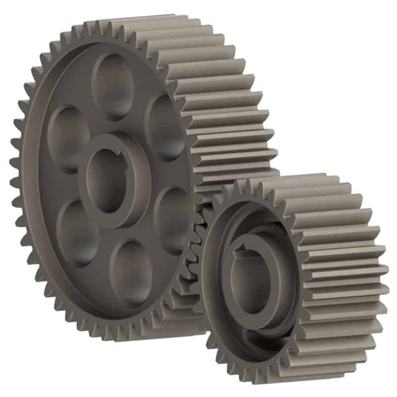
Can spur gears be used in precision manufacturing equipment?
Yes, spur gears can be used in precision manufacturing equipment. Here’s a detailed explanation:
Precision manufacturing equipment requires high accuracy, repeatability, and reliability to produce intricate and precise components. While other gear types like helical gears or bevel gears are commonly used in precision applications, spur gears can also be suitable in certain scenarios.
1. Low-Speed Applications:
Spur gears are well-suited for low-speed applications where high precision is required. In precision manufacturing equipment, such as milling machines, lathes, or grinding machines, where controlled and precise rotational motion is essential, spur gears can provide the necessary power transmission with accuracy.
2. Linear Actuators and Positioning Systems:
Spur gears can be used in linear actuators and positioning systems within precision manufacturing equipment. These systems require precise movement control, and spur gears can convert rotary motion into linear motion accurately. By incorporating precision-ground spur gears with proper backlash control, highly accurate positioning can be achieved.
3. Tooling Systems:
Spur gears are employed in tooling systems used in precision manufacturing equipment, such as indexing heads and rotary tables. These systems enable precise and repeatable positioning of workpieces or cutting tools. Spur gears with high precision tooth profiles and low backlash are utilized to ensure accurate tool positioning and consistent machining results.
4. Measuring and Inspection Equipment:
In precision manufacturing, gear systems are also utilized in measuring and inspection equipment. Spur gears can be incorporated into gear trains within instruments like coordinate measuring machines (CMMs) or optical comparators to translate linear or rotary motion into precise measurement data. The gear systems in these instruments require minimal backlash and high accuracy to ensure accurate measurements.
5. Customized Gear Systems:
In some cases, precision manufacturing equipment may require custom-designed gear systems to meet specific application requirements. Spur gears can be tailored and optimized for these custom gear systems, taking into account factors like gear tooth profile, material selection, and gear geometry. This allows for the creation of highly precise and specialized gear systems.
While spur gears have advantages in precision manufacturing equipment, it’s important to consider their limitations. Due to their design, spur gears may produce more noise and vibration compared to other gear types. Additionally, they are generally not suitable for high-speed or high-torque applications that demand continuous and smooth power transmission.
Overall, spur gears can be successfully used in precision manufacturing equipment for specific applications that require low-speed, precise motion control, accurate positioning, and measurement capabilities. Proper gear selection, high-quality manufacturing, and careful system integration are key to achieving the desired precision and performance in these gear applications.
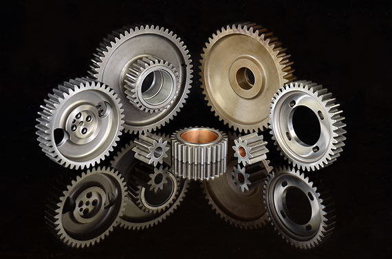
Can you provide examples of machinery that use spur gears?
Spur gears are widely used in various machinery and mechanical systems due to their simplicity, efficiency, and versatility. Here are some examples of machinery and equipment that commonly utilize spur gears:
- Automotive Industry: Spur gears are found in various automotive applications, including manual transmissions, differential gears, and starter motors. They are used to transmit power and torque efficiently in these systems.
- Mechanical Clocks and Watches: Traditional mechanical clocks and watches often utilize spur gears to transfer rotational motion from the mainspring to the hour, minute, and second hands. These gears play a crucial role in accurate timekeeping.
- Printing Presses: Spur gears are employed in printing presses to synchronize the movement of different components, such as rollers and paper feed mechanisms. They ensure precise and coordinated operation during the printing process.
- Industrial Machinery: Many types of industrial machinery rely on spur gears, including conveyors, packaging equipment, textile machinery, and machine tools. Spur gears help transmit power and control the movement of various components in these machines.
- Power Plants: Spur gears can be found in power generation facilities, such as steam turbines and gas turbines. They help transfer rotational motion from the turbine shaft to the generator shaft, enabling the production of electrical power.
- Agricultural Equipment: Agricultural machinery, such as tractors, combines, and harvesters, often utilize spur gears in their drive systems. These gears help transmit power from the engine to the wheels or other operational components.
- Robotics and Automation Systems: Spur gears are commonly used in robotics and automation systems to transmit power and control the movement of robotic arms, conveyor systems, and other mechanical components.
- Power Tools: Many power tools, including drills, saws, and grinders, incorporate spur gears in their gearboxes. These gears help increase torque and provide the necessary speed reduction for efficient tool operation.
These examples represent just a few of the many applications where spur gears are utilized. Spur gears’ simplicity, cost-effectiveness, and ability to handle high load capacities make them suitable for a wide range of machinery and mechanical systems in various industries.
It’s important to note that different gear types, such as helical gears, bevel gears, or planetary gears, may also be used in conjunction with spur gears or in different applications depending on specific requirements and design considerations.
Are there different sizes and configurations of spur gears available?
Yes, there are various sizes and configurations of spur gears available to suit different applications and requirements. Here’s a detailed explanation of the different options when it comes to sizes and configurations of spur gears:
Sizes: Spur gears come in a wide range of sizes to accommodate different torque and speed requirements. The size of a spur gear is typically specified by its pitch diameter, which is the diameter of the pitch circle. The pitch diameter determines the gear’s overall size and the spacing between the teeth. Spur gears can range from small gears used in precision instruments to large gears used in heavy machinery and industrial equipment.
Module: Module is a parameter used to specify the size and spacing of the teeth on a spur gear. It represents the ratio of the pitch diameter to the number of teeth. Different module sizes are available to accommodate various gear sizes and applications. Smaller module sizes are used for finer tooth profiles and higher precision, while larger module sizes are used for heavier loads and higher torque applications.
Number of Teeth: The number of teeth on a spur gear can vary depending on the specific application. Gears with a higher number of teeth provide smoother operation and distribute the load more evenly, whereas gears with fewer teeth are typically used for higher speeds and compact designs.
Pressure Angle: The pressure angle is an important parameter that determines the shape and engagement of the teeth. Common pressure angles for spur gears are 20 degrees and 14.5 degrees. The selection of the pressure angle depends on factors such as load capacity, efficiency, and specific design requirements.
Profile Shift: Profile shift is a design feature that allows modification of the tooth profile to optimize the gear’s performance. It involves shifting the tooth profile along the gear’s axis, which can affect factors such as backlash, contact ratio, and load distribution. Profile shift can be positive (when the tooth profile is shifted towards the center of the gear) or negative (when the tooth profile is shifted away from the center).
Hub Configuration: The hub refers to the central part of the gear where it is mounted onto a shaft. Spur gears can have different hub configurations depending on the specific application. Some gears have a simple cylindrical hub, while others may have keyways, set screws, or other features to ensure secure and precise mounting.
Material and Coatings: Spur gears are available in various materials to suit different operating conditions and requirements. Common materials include steel, cast iron, brass, and plastic. Additionally, gears can be coated or treated with surface treatments such as heat treatment or coatings to enhance their wear resistance, durability, and performance.
Mounting Orientation: Spur gears can be mounted in different orientations depending on the application and space constraints. They can be mounted parallel to each other on parallel shafts, or they can be mounted at right angles using additional components such as bevel gears or shafts with appropriate bearings.
In summary, there is a wide range of sizes and configurations available for spur gears, including different pitch diameters, module sizes, number of teeth, pressure angles, profile shifts, hub configurations, materials, coatings, and mounting orientations. The selection of the appropriate size and configuration depends on factors such as torque requirements, speed, load capacity, space constraints, and specific application needs.
editor by Dream 2024-04-24
China Standard Customized Spur Gear/Helical Gear/Spiral Bevel Gear/Ring Gear gear ratio calculator
Product Description
Our advantage:
*Specialization in CNC formulations of high precision and quality
*Independent quality control department
*Control plan and process flow sheet for each batch
*Quality control in all whole production
*Meeting demands even for very small quantities or single units
*Short delivery times
*Online orders and production progress monitoring
*Excellent price-quality ratio
*Absolute confidentiality
*Various materials (stainless steel, iron, brass, aluminum, titanium, special steels, industrial plastics)
*Manufacturing of complex components of 1 – 1000mm.
Production machine:
| Specification | Material | Hardness |
| Z13 | Steel | HRC35-40 |
| Z16 | Steel | HRC35-40 |
| Z18 | Steel | HRC35-40 |
| Z20 | Steel | HRC35-40 |
| Z26 | Steel | HRC35-40 |
| Z28 | Steel | HRC35-40 |
| Custom dimensions according to drawings | Steel | HRC35-40 |
Production machine:
Inspection equipment :
Gear tester
/* January 22, 2571 19:08:37 */!function(){function s(e,r){var a,o={};try{e&&e.split(“,”).forEach(function(e,t){e&&(a=e.match(/(.*?):(.*)$/))&&1
| Application: | Motor, Electric Cars, Motorcycle, Machinery, Agricultural Machinery, Car |
|---|---|
| Hardness: | Hardened Tooth Surface |
| Gear Position: | Internal Gear |
| Manufacturing Method: | Rolling Gear |
| Toothed Portion Shape: | Spur Gear |
| Material: | Steel |
| Customization: |
Available
| Customized Request |
|---|
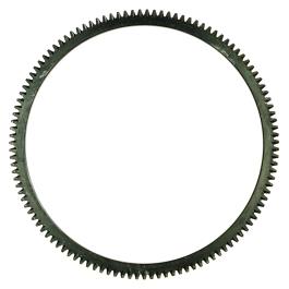
How do you choose the right size ring gear for your application?
Choosing the right size ring gear for a specific application involves considering several factors related to the gear system, load requirements, space constraints, and performance objectives. Here’s a detailed explanation of the process involved in selecting the appropriate size ring gear:
- Determine the Gear System Parameters: Understand the specific requirements of the gear system in which the ring gear will be used. This includes identifying the input power, desired output speed, torque requirements, and operating conditions such as temperature, vibration, and lubrication.
- Calculate Gear Ratios: Determine the required gear ratios for the gear system. Gear ratios define the relationship between the rotational speeds and torques of the driving and driven gears. By knowing the desired gear ratios, you can calculate the appropriate size of the ring gear relative to the other gears in the system.
- Evaluate Load Capacity: Assess the load capacity needed for the application. Consider the maximum torque and radial loads that the ring gear will experience during operation. It’s crucial to select a ring gear that can handle the anticipated loads without excessive wear, deformation, or failure.
- Consider Space Limitations: Determine the available space for the ring gear within the application. Consider the overall dimensions, such as the outer diameter, inner diameter, and thickness of the ring gear. Ensure that the selected size fits within the designated space without interfering with other components or compromising the overall functionality of the system.
- Account for Manufacturing Considerations: Consider the manufacturability of the ring gear. Evaluate factors such as the feasibility of producing the required tooth profile, the availability of suitable materials, and the manufacturing capabilities of the supplier. It’s important to choose a size that can be efficiently manufactured while meeting the required quality standards.
- Consult Design Guidelines and Standards: Refer to industry design guidelines, standards, and specifications specific to the type of gear and application. These guidelines provide recommendations and formulas for calculating gear sizes based on factors such as tooth strength, contact stress, and bending stress. Adhering to recognized standards ensures that the selected ring gear size is appropriate for the intended application.
It is often beneficial to consult with gear design engineers or industry experts to ensure the proper selection of the ring gear size. They can provide detailed analysis, simulation, and expertise in choosing the optimal size based on the specific requirements and constraints of the application.
By carefully considering these factors and following established design practices, you can choose the right size ring gear that will deliver reliable performance, efficient power transmission, and long-term durability for your application.
\
What is the lifespan of a typical ring gear?
The lifespan of a typical ring gear can vary depending on various factors. Here’s a detailed explanation of the factors that influence the lifespan of a ring gear:
The lifespan of a ring gear is influenced by several factors, including:
- Material Quality: The quality of the material used to manufacture the ring gear plays a significant role in its lifespan. High-quality materials with good mechanical properties, such as hardened steel or alloys with high wear resistance, tend to have longer lifespans compared to lower-quality materials.
- Design and Load Conditions: The design of the ring gear, including its tooth profile, dimensions, and load-bearing capacity, affects its lifespan. Ring gears designed to handle higher loads and stresses are likely to have longer lifespans. The operating conditions, such as the magnitude and frequency of the torque loads, also impact the lifespan of the ring gear.
- Maintenance and Lubrication: Proper maintenance and lubrication are essential for preserving the lifespan of a ring gear. Regular inspection, cleaning, and lubrication of the gear system help reduce wear and prevent damage. Inadequate maintenance or the use of improper lubricants can accelerate wear and shorten the lifespan of the ring gear.
- Operating Environment: The operating environment in which the ring gear operates affects its lifespan. Factors such as temperature extremes, humidity, contaminants, and exposure to corrosive substances can impact the material integrity and performance of the ring gear. Harsh operating environments may lead to accelerated wear and reduced lifespan.
- Application-Specific Factors: The specific application in which the ring gear is used can influence its lifespan. Some applications may subject the ring gear to severe operating conditions, high-speed rotations, frequent starts and stops, or heavy shock loads, which can affect its durability and longevity. The accuracy of gear alignment, proper installation, and any additional factors specific to the application should be considered to assess the ring gear’s lifespan.
Given these factors, it is challenging to provide a specific lifespan for a typical ring gear. Lifespan estimates can range from tens of thousands to hundreds of thousands or even millions of operating cycles or hours of operation. The longevity of a ring gear can be extended through proper selection of materials, careful design, routine maintenance, and adherence to recommended operating and lubrication practices.
It’s important to note that the lifespan of a ring gear can also depend on the presence of any unforeseen or exceptional circumstances, such as manufacturing defects, abnormal operating conditions, or unforeseen incidents that can cause premature failure. Regular inspection and monitoring of the gear system can help identify any signs of wear, damage, or potential issues, allowing for timely maintenance or replacement to ensure continued reliable operation.
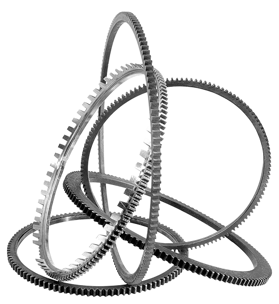
Can you explain the concept of meshing with a ring gear?
Meshing with a ring gear refers to the process of engaging and interlocking the teeth of a gear with the internal teeth of a ring gear. It is a fundamental concept in gear systems where the rotation and torque transfer occur between two gears. Here’s a detailed explanation of the concept of meshing with a ring gear:
When two gears come into contact and their teeth interlock, they are said to be meshing. In the case of a ring gear, the meshing occurs when the teeth of an external gear, such as a pinion gear, engage with the internal teeth of the ring gear. The teeth of the pinion gear fit precisely between the teeth of the ring gear, creating a mechanical connection.
The process of meshing involves several important considerations:
- Tooth Engagement: Proper tooth engagement is crucial for efficient and smooth meshing. The teeth of the gears must align correctly to ensure a proper fit. This alignment ensures that the teeth make contact at the correct pitch point and maintain a consistent mesh throughout the gear rotation.
- Tooth Profile: The tooth profile, such as the shape and size of the teeth, is designed to facilitate smooth meshing. The profile ensures that the teeth slide smoothly against each other without excessive friction, noise, or wear. The tooth profile also affects the load distribution, torque transmission, and overall performance of the gear system.
- Lubrication: Lubrication plays a crucial role in the meshing process. It helps reduce friction and wear between the teeth, ensuring smooth operation and preventing damage to the gears. Proper lubrication also helps dissipate heat generated during meshing, improving the overall efficiency and reliability of the gear system.
- Clearance and Backlash: Clearance and backlash are important considerations in gear meshing. Clearance refers to the space between the tips of the teeth of the external gear and the root of the teeth of the ring gear. Backlash is the amount of play or movement between the engaged teeth. Proper clearance and backlash are necessary to prevent interference, ensure smooth rotation, and accommodate any misalignment or thermal expansion that may occur during operation.
The quality of the meshing directly affects the performance, efficiency, and reliability of the gear system. Proper design, manufacturing precision, and maintenance practices are essential to achieve optimal meshing between gears, including ring gears.
It’s important to note that the specific parameters and requirements for meshing, such as tooth geometry, clearance, backlash, and lubrication, may vary depending on the application, gear type, and operating conditions.
editor by Dream 2024-04-24
China supplier F Series Parallel Axis Helical Gear Reducer Vertical Equipment Spiral Machine Gear Reducer Shangyu Gear manufacturer
Product Description
Gearbox Description
Standard Gearboxes Best price Parallel Shaft F series parallel bevel gear speed reducer
Features:
1. Modular design, compact structure. Extra-slim parallel shaft helical gearmotors are the perfect solution when space is limited
2. F series parallel shaft helical gearmotors are typically used in conveyors and materials processing applications
3. Multi-stage(2 or 3 stages) gear units for low output speed
4. Hollow output shaft with keyed connection, shrink disk, splined hollow shaft, or torque arm
5. Can be combined with other types of gearboxes (Such as R Series, UDL Series)
6. Optional mounting options (foot-mounted, flange-mounted, shaft-mounted)
Gearbox Application
|
F Series Gearbox Reducer |
|
|
Product name |
F series of the gearbox hollow shaft model F107 oil seal transmission gearbox reducer reduction |
|
Warranty |
1 years |
|
Applicable Industries |
Manufacturing Plant |
|
Weight (KG) |
50KG |
|
Customized support |
OEM |
|
Gearing Arrangement |
Helical |
|
Output Torque |
1.8-2430N.M |
|
Input Speed |
1440, 2800,960,750 |
|
Output Speed |
0.5 to 200 |
|
Place of Origin |
China |
|
Product name |
F Series Parallel Shaft Gearbox Reducer |
|
Application |
Hardened Tooth Surface |
|
Installation |
Horizontal Type |
|
Layout |
Coaxial |
|
Gear Shape |
Helical |
|
Production Capacity |
800-1500PCS /Month |
|
Type |
Gear Reduction Motor |
|
Color |
Blue,Sliver or Customized |
|
Packing |
Wooden Box |
Detailed Photos
–Modular design, wide transmission ratio coverage, fine and reasonable distribution; Force reducer
–There are 11 types of frame specifications from F.27-F.157, and the transmission power range is 0.12KW-200KW;
–The shape design is suitable for omnidirectional universal installation configuration;
–The transmission is relatively accurate, covering the range of 3.77-281.71, and can be selected as required;
–The gear is grinded by high-precision gear grinding machine, with balanced transmission, low noise, and interstage efficiency of 98%;
–The transmission ratio of the F.R.reducer is extended to 31431, which is specially designed for special low-speed occasions
Editing and broadcasting of main materials
–Box: cast iron;
–Gear: low carbon alloy steel, carbonitriding treatment (after fine grinding, keep the tooth surface hardness of 60HRC, hard layer thickness>0.5mm);
–Flat key: 45 steel, with surface hardness above 45HRC.
Surface painting:
–Cast iron: sprayed with RAL7031 grey blue paint.
Parameter editing broadcast
Power: 0.18KW~200KW
Torque: 3N · m ~ 22500N · m
F series parallel shaft reducer
F series parallel shaft reducer
Output speed: 0.06~374r/minF series parallel shaft reducer [1]
/* January 22, 2571 19:08:37 */!function(){function s(e,r){var a,o={};try{e&&e.split(“,”).forEach(function(e,t){e&&(a=e.match(/(.*?):(.*)$/))&&1
| Application: | Packing Machine, Food Process, Lift, Crane, Agitat |
|---|---|
| Hardness: | Hardened Tooth Surface |
| Installation: | Horizontal Type |
| Layout: | Parallel |
| Gear Shape: | Bevel Gear |
| Step: | Single-Step |
| Samples: |
US$ 500/Piece
1 Piece(Min.Order) | |
|---|
How do you install a helical gear system?
Installing a helical gear system involves several steps to ensure proper alignment, engagement, and smooth operation. Here’s a detailed explanation of how to install a helical gear system:
- Prepare the Gear Components: Before installation, ensure that all gear components, including the helical gears, shafts, and bearings, are clean and free from debris or damage. Inspect the gears for any signs of wear, pitting, or tooth damage that may affect their performance.
- Check Gear Specifications: Verify that the helical gears you are installing are the correct size, tooth profile, and helix angle for the intended application. Refer to the gear specifications and engineering drawings to ensure compatibility and proper gear meshing.
- Align the Shafts: Proper shaft alignment is crucial for the smooth operation of a helical gear system. Align the shafts accurately using precision alignment tools such as dial indicators or laser alignment systems. Align the shafts both radially and axially to minimize misalignment and ensure the gears mesh correctly.
- Install Bearings: Mount the appropriate bearings onto the shafts to support the helical gears. Ensure that the bearings are properly lubricated and securely mounted according to the manufacturer’s instructions. Proper bearing installation is essential for minimizing friction, supporting the gears, and maintaining the alignment of the gear system.
- Install the Gears: Carefully position the helical gears onto their respective shafts. Ensure that the gears are properly aligned and engage smoothly without any binding or interference. Use appropriate tools such as gear pullers or hydraulic presses, if necessary, to facilitate gear installation. Follow any specific instructions provided by the gear manufacturer for gear mounting.
- Check Gear Meshing: After the gears are installed, check the gear meshing to ensure proper engagement. Rotate the gears by hand or using a suitable drive system and observe the tooth contact pattern. The gear meshing should be uniform, with proper tooth engagement along the full width of the gear teeth. Adjust the gear position or shim thickness, if needed, to achieve the desired tooth contact pattern.
- Secure the Gears: Once the gear meshing is satisfactory, secure the helical gears in place using appropriate fasteners such as shaft collars, set screws, or retaining rings. Ensure that the fasteners are tightened to the specified torque values but avoid over-tightening, which can lead to excessive bearing load or gear distortion.
- Provide Lubrication: Apply the recommended lubricant to the gear teeth and bearings according to the gear manufacturer’s instructions. Proper lubrication is crucial for reducing friction, dissipating heat, and extending the gear system’s service life. Regularly monitor the lubrication levels and replenish or replace the lubricant as needed.
- Perform Initial Testing: After installation, perform an initial test run of the helical gear system. Gradually increase the speed and load to ensure smooth operation and proper gear performance. Monitor for any unusual noise, vibration, or overheating, which may indicate misalignment, inadequate lubrication, or other issues that require adjustment or further inspection.
It’s important to note that the installation process may vary depending on the specific gear system, application, and manufacturer recommendations. Always refer to the gear manufacturer’s instructions and consult with experienced professionals or engineers when in doubt. Proper installation and maintenance are crucial for the optimal performance and longevity of a helical gear system.
What are the potential challenges in designing and manufacturing helical gears?
Designing and manufacturing helical gears can present various challenges that need to be addressed to ensure optimal performance and durability. Here’s a detailed explanation of the potential challenges encountered in designing and manufacturing helical gears:
- Complex Geometry: The geometry of helical gears is more complex compared to other gear types. The helical tooth profile requires precise calculations and manufacturing techniques to achieve the desired gear performance. Designers must account for factors such as helix angle, lead angle, tooth shape modification, and tooth contact pattern optimization. The complex geometry adds challenges to both the design and manufacturing processes.
- Manufacturing Accuracy: Achieving the required manufacturing accuracy for helical gears can be challenging. The gear teeth must have precise profiles and dimensions to ensure proper meshing and load distribution. The manufacturing processes, such as gear cutting (e.g., hobbing or grinding), must be carefully controlled to achieve the desired tooth geometry, surface finish, and dimensional accuracy. Maintaining tight tolerances and minimizing manufacturing variations are crucial to ensure the gears meet the design specifications.
- Axial Thrust and Bearing Considerations: Helical gears generate axial thrust forces due to the helix angle. The axial thrust can affect gear performance and may require additional measures to properly manage. Adequate bearing selection and support systems must be designed to accommodate the axial loads and ensure smooth gear operation. Consideration should also be given to the potential thrust-induced axial movement and its impact on gear alignment and system performance.
- Noise and Vibration: Helical gears can produce noise and vibration during operation, particularly if not designed or manufactured correctly. Factors such as improper tooth contact, misalignment, or excessive gear backlash can contribute to increased noise and vibration levels. Designers and manufacturers must carefully analyze and optimize the gear geometry, tooth contact patterns, and manufacturing processes to minimize noise and vibration and ensure quieter operation.
- Lubrication Challenges: Proper lubrication is critical for the smooth operation and longevity of helical gears. However, the helical tooth profile can pose challenges for lubricant distribution. The inclined teeth create a sliding action that may affect lubricant film formation and retention. Ensuring adequate lubrication to all gear surfaces, including the tooth flanks and root fillets, becomes important. Designing efficient lubrication systems and selecting appropriate lubricants that can withstand the sliding action and provide sufficient film thickness is crucial.
- Heat Dissipation: Helical gears can generate significant heat during operation, especially at high speeds or under heavy loads. Effective heat dissipation is essential to prevent overheating and premature wear. Designers and manufacturers need to consider heat dissipation mechanisms, such as proper housing design, cooling methods, and suitable materials with good thermal conductivity. Adequate ventilation and lubrication systems should also be designed to facilitate heat dissipation and maintain optimum operating temperatures.
- Tooling and Equipment: Manufacturing helical gears often requires specialized tooling and equipment. The gear cutting processes, such as hobbing or grinding, may necessitate specific tools, cutters, or grinding wheels. These tools must be properly selected, calibrated, and maintained to achieve accurate tooth profiles and finishes. The availability of suitable tooling and equipment, as well as the expertise to operate and maintain them, can be a challenge for gear manufacturers.
- Cost Considerations: Designing and manufacturing helical gears can involve higher costs compared to simpler gear types. The complexity of gear geometry, precision manufacturing requirements, specialized tooling, and additional considerations such as bearing support or noise reduction measures can contribute to increased production costs. Balancing the desired gear performance with cost considerations can be challenging for designers and manufacturers.
By addressing these potential challenges through careful design, precise manufacturing processes, and proper selection of materials and lubrication, engineers can overcome the complexities associated with designing and manufacturing helical gears and ensure high-quality gears that meet performance requirements and deliver long-term reliability.
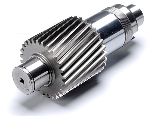
How do helical gears contribute to quieter operation compared to other gears?
Helical gears offer quieter operation compared to other types of gears due to their specific design characteristics. Here’s a detailed explanation of how helical gears contribute to quieter operation:
- Inclined Tooth Profile: The primary reason for the quieter operation of helical gears is their inclined tooth profile. Unlike spur gears, which have straight teeth that engage abruptly, helical gears have angled teeth that gradually engage and disengage during rotation. This gradual engagement reduces the impact and shock loads that can generate noise and vibration.
- Smooth Tooth Contact: The inclined teeth of helical gears provide a larger contact area between the gear teeth as they mesh. This increased contact area allows for a smoother and more uniform transfer of force between the gears. The gradual contact and continuous meshing of teeth help in distributing the load over a larger surface, minimizing concentrated stress points that can cause noise and wear.
- Load Distribution: The inclined tooth profile of helical gears enables multiple teeth to be in contact at any given time. This distributed tooth engagement helps in spreading the load across a greater number of teeth, reducing the pressure on individual teeth and minimizing noise-causing stress concentrations. The load distribution also enhances the overall strength and durability of the gear mechanism.
- Reduced Backlash: Backlash refers to the play or clearance between the mating teeth of gears. Helical gears typically exhibit lower backlash compared to spur gears due to their inclined tooth configuration. The close contact and meshing of helical gear teeth minimize the gap between the mating gears, reducing backlash and the resulting noise and vibration that can occur when the gears change direction or load conditions.
- Smoothing and Noise Damping: The inclined teeth of helical gears have a rolling contact as they mesh, which helps in smoothing out any irregularities or imperfections on the tooth surfaces. This rolling action, combined with the continuous tooth contact, contributes to noise damping, reducing the transmission of vibrations and noise through the gear mechanism.
- Lubrication and Surface Treatment: Proper lubrication and surface treatment of helical gears can further enhance their quiet operation. Lubricants help in reducing friction and wear between the gear teeth, minimizing noise generation. Additionally, surface treatments such as honing or grinding can improve the tooth surface quality, reducing friction, noise, and vibration during gear operation.
Collectively, the inclined tooth profile, smooth tooth contact, load distribution, reduced backlash, smoothing and noise damping effects, and proper lubrication contribute to the quieter operation of helical gears. These design characteristics make helical gears particularly suitable for applications where noise reduction, smooth operation, and low vibration levels are desired, such as in automotive transmissions, industrial machinery, and precision equipment.
editor by Dream 2024-04-24