Product Description
Key attributes
Other attributes
Applicable Industries
Manufacturing Plant, Machinery Repair Shops, Construction works
Weight (KG)
2000
Showroom Location
None
Video outgoing-inspection
Not Available
Machinery Test Report
Provided
Marketing Type
Ordinary Product
Warranty of core components
1 Year
Core Components
Gear
Place of CHINAMFG
ZheJiang , China
Condition
New
Warranty
1.5 years
Shape
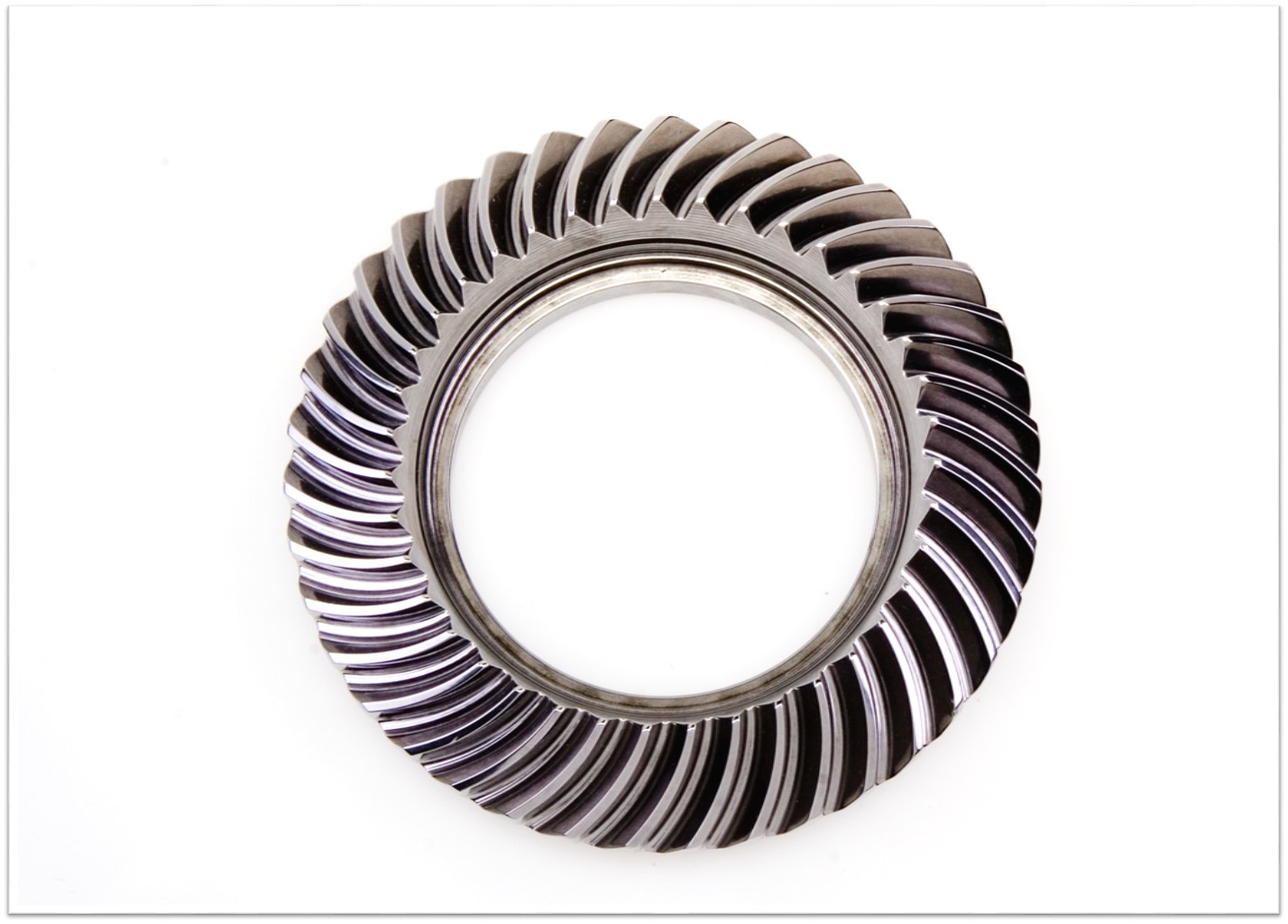
Ring Gear
Standard or Nonstandard
Nonstandard
Tooth Profile
spur gear/helical gear/customized
Material
Steel
Processing
casting,Forging,hobbing
Pressure Angle
20/40/50/60 Customized
Brand Name
TS
Material
steel, stainless steel customized
Precision
standard precision grade per request
Technique
casting/forging/ customized
Heat Treatment
avaliable
Tooth Profile
Internal Spur/external spur/etc
Features
Professional Production
Application
Industry Machinery
Applicable Standard
ISO/DIN
Gear precision
ordinary/ 8e/7e/6e
Service
Customized OEM
Packaging and delivery
Packaging Details
TS Packaging Details:
1. Bearing surface is covered with the anti-rust oil first; And then wrapped with the plastic film;
2. And then packed with Kraft paper and professional belts;
3. At last, with wooden box totally at the outer packing to in void the rust or the moist;
4. Packaging can be done according to customer’s requirements.
Port
China any Port
Supply Ability
Supply Ability
1500 Set/Sets per Month
Show less
Lead time
| Quantity (sets) | 1 – 1 | > 1 |
| Lead time (days) | 30 | To be negotiated |
OUR WORKSHOPS
OUR EQUIPMENTS
Technology Process
|
Material |
Carbon steel,Alloy steel |
||
|
Structure |
Forging,casting |
||
|
Type of gear |
spur gear,helical gear,Planetary Gear |
||
|
Heat treatment |
Quenching and tempering |
||
|
Process |
forging, rough machining, QT, finish machining |
||
|
Main equipments |
hobbing,CNC machine |
||
|
Module |
up to 200 |
||
|
Precision of gear |
Grinding ISO Grade 5-7 & Hobbing ISO Grade 8-9 |
||
|
Inspection |
Raw material inspection, UT,physical property test,dimension inspect |
||
|
Application |
Mining machinery, mill, kiln and other equipment |
||
OUR CERTIFICATE
OUR CUSTOMER FEEDBACK
CONTACT
/* January 22, 2571 19:08:37 */!function(){function s(e,r){var a,o={};try{e&&e.split(“,”).forEach(function(e,t){e&&(a=e.match(/(.*?):(.*)$/))&&1
| Application: | Industry |
|---|---|
| Hardness: | Hb190-Hb300 |
| Gear Position: | External Gear |
| Samples: |
US$ 100/Piece
1 Piece(Min.Order) | Order Sample |
|---|
| Customization: |
Available
| Customized Request |
|---|
.shipping-cost-tm .tm-status-off{background: none;padding:0;color: #1470cc}
| Shipping Cost:
Estimated freight per unit. |
about shipping cost and estimated delivery time. |
|---|
| Payment Method: |
|
|---|---|
|
Initial Payment Full Payment |
| Currency: | US$ |
|---|
| Return&refunds: | You can apply for a refund up to 30 days after receipt of the products. |
|---|
Are there different types of ring gears available?
Yes, there are different types of ring gears available to suit various applications and functional requirements. Here’s a detailed explanation of the different types of ring gears:
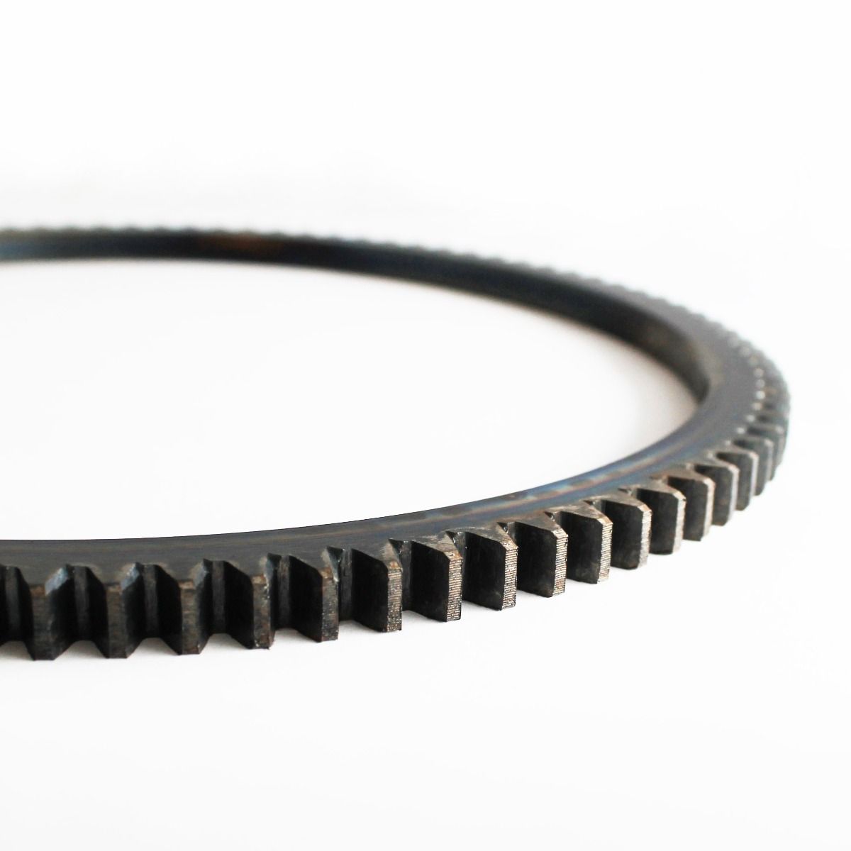
- External Ring Gears: External ring gears, also known as external annular gears, have teeth on the outer circumference of the gear. These gears mesh with an internal gear or a pinion gear. External ring gears are commonly used in applications where the gear rotation needs to be transferred to an internal gear or where a high gear ratio is desired.
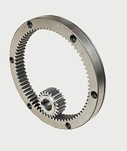
- Internal Ring Gears: Internal ring gears, also known as internal annular gears, have teeth on the inner circumference of the gear. These gears mesh with an external gear or a pinion gear. Internal ring gears are frequently used in applications where the gear rotation needs to be transmitted to an external gear or where a compact gear assembly is required.
- Segmental Ring Gears: Segmental ring gears are ring gears that are divided into segments or sectors. Each segment has a portion of the gear’s circumference with teeth. These segments can be individually mounted or assembled together to form a complete ring gear. Segmental ring gears are used in applications where flexibility in gear installation or replacement is necessary, such as large-scale gear systems or machinery with limited access.
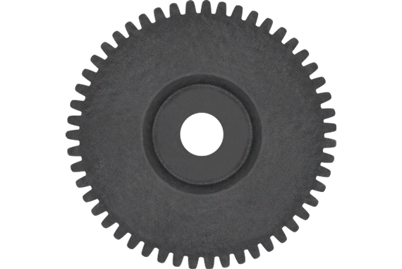
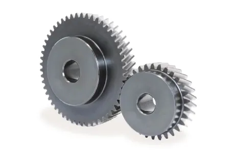
- Spur Ring Gears: Spur ring gears have straight teeth that are parallel to the gear’s axis of rotation. These gears offer simple and efficient operation with high gear ratios. Spur ring gears are commonly used in applications that require precise motion control, such as robotics, automotive transmissions, and industrial machinery.
- Helical Ring Gears: Helical ring gears have teeth with a helix angle. The helical teeth form a helical or spiral pattern around the gear’s circumference. Helical ring gears provide smoother and quieter operation compared to spur ring gears due to the gradual engagement of the teeth. They are often used in applications that demand high torque transmission, such as heavy machinery, marine propulsion systems, and power generation equipment.
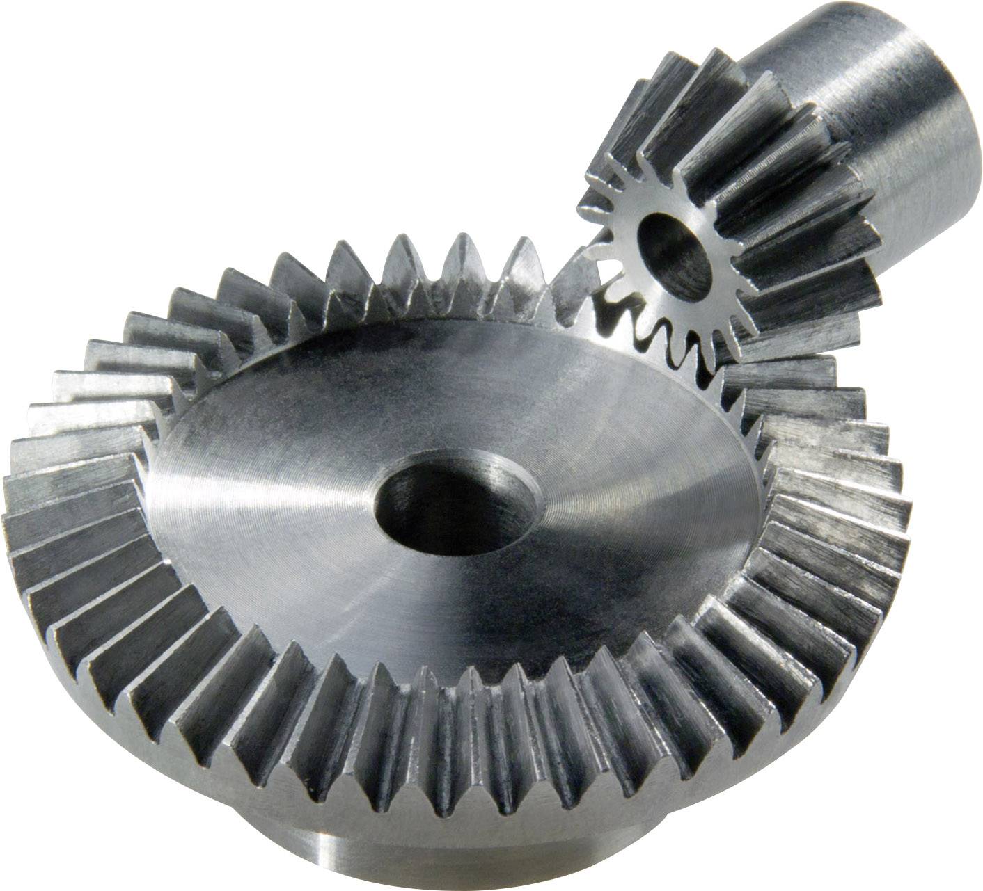
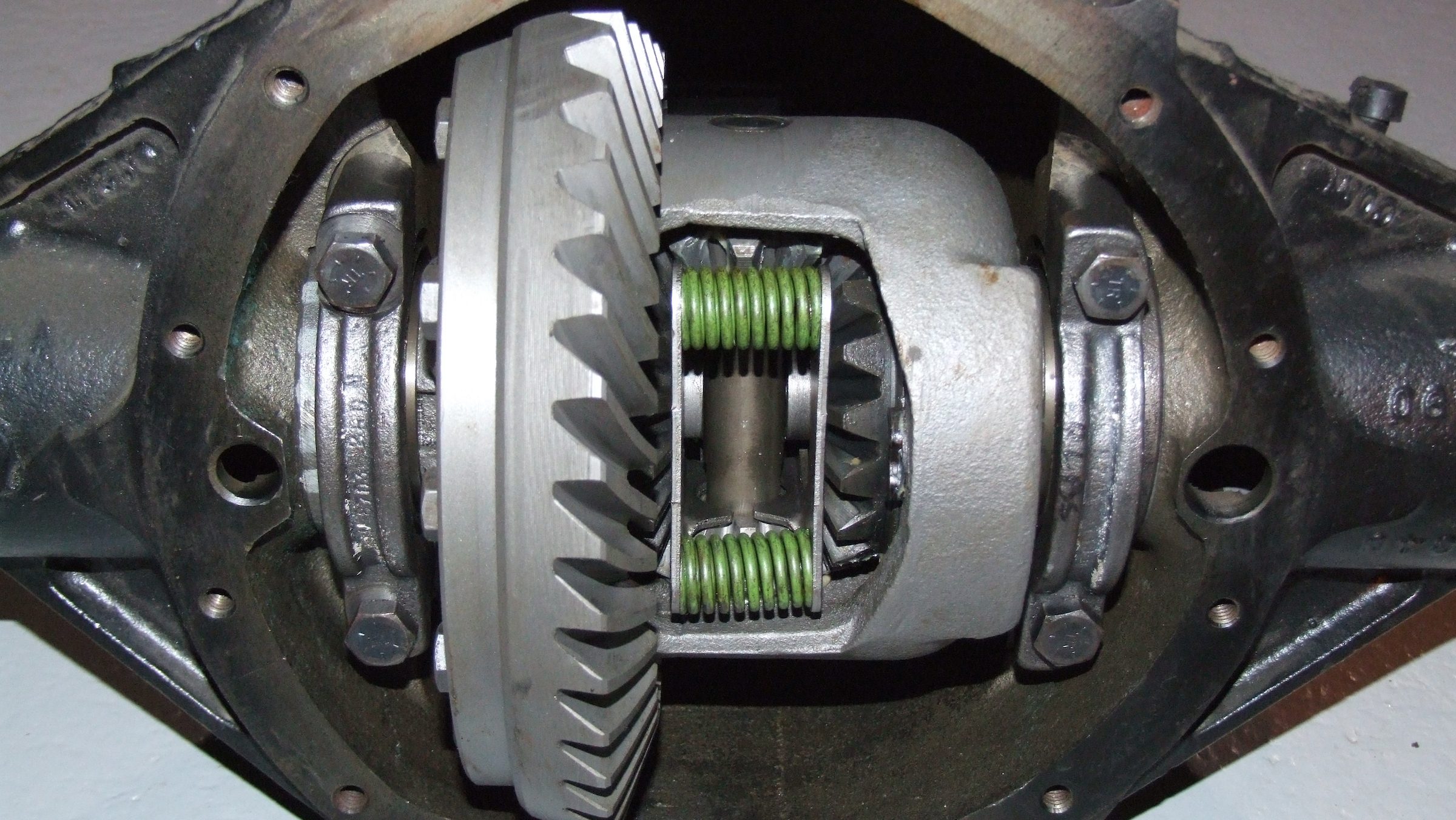
- Bevel Ring Gears: Bevel ring gears have teeth that are conically shaped and intersect the gear’s axis of rotation. These gears are used in applications that require the transmission of motion and torque between shafts that are not parallel but intersect at an angle. Bevel ring gears are commonly found in automotive differentials, hand tools, and various industrial machinery.
- Planetary Ring Gears: Planetary ring gears are part of planetary gear systems, which consist of multiple gears arranged in a planetary configuration. The ring gear serves as the stationary outer gear, while other gears, such as sun gears and planet gears, revolve around it. Planetary ring gears are used in applications that require compact and efficient gear systems, such as automotive transmissions, robotics, and aerospace mechanisms.
The specific type of ring gear chosen for a particular application depends on factors such as load requirements, space limitations, gear ratios, operating conditions, and desired performance characteristics.
What is the lifespan of a typical ring gear?
The lifespan of a typical ring gear can vary depending on various factors. Here’s a detailed explanation of the factors that influence the lifespan of a ring gear:
The lifespan of a ring gear is influenced by several factors, including:
- Material Quality: The quality of the material used to manufacture the ring gear plays a significant role in its lifespan. High-quality materials with good mechanical properties, such as hardened steel or alloys with high wear resistance, tend to have longer lifespans compared to lower-quality materials.
- Design and Load Conditions: The design of the ring gear, including its tooth profile, dimensions, and load-bearing capacity, affects its lifespan. Ring gears designed to handle higher loads and stresses are likely to have longer lifespans. The operating conditions, such as the magnitude and frequency of the torque loads, also impact the lifespan of the ring gear.
- Maintenance and Lubrication: Proper maintenance and lubrication are essential for preserving the lifespan of a ring gear. Regular inspection, cleaning, and lubrication of the gear system help reduce wear and prevent damage. Inadequate maintenance or the use of improper lubricants can accelerate wear and shorten the lifespan of the ring gear.
- Operating Environment: The operating environment in which the ring gear operates affects its lifespan. Factors such as temperature extremes, humidity, contaminants, and exposure to corrosive substances can impact the material integrity and performance of the ring gear. Harsh operating environments may lead to accelerated wear and reduced lifespan.
- Application-Specific Factors: The specific application in which the ring gear is used can influence its lifespan. Some applications may subject the ring gear to severe operating conditions, high-speed rotations, frequent starts and stops, or heavy shock loads, which can affect its durability and longevity. The accuracy of gear alignment, proper installation, and any additional factors specific to the application should be considered to assess the ring gear’s lifespan.
Given these factors, it is challenging to provide a specific lifespan for a typical ring gear. Lifespan estimates can range from tens of thousands to hundreds of thousands or even millions of operating cycles or hours of operation. The longevity of a ring gear can be extended through proper selection of materials, careful design, routine maintenance, and adherence to recommended operating and lubrication practices.
It’s important to note that the lifespan of a ring gear can also depend on the presence of any unforeseen or exceptional circumstances, such as manufacturing defects, abnormal operating conditions, or unforeseen incidents that can cause premature failure. Regular inspection and monitoring of the gear system can help identify any signs of wear, damage, or potential issues, allowing for timely maintenance or replacement to ensure continued reliable operation.
Can you explain the concept of meshing with a ring gear?
Meshing with a ring gear refers to the process of engaging and interlocking the teeth of a gear with the internal teeth of a ring gear. It is a fundamental concept in gear systems where the rotation and torque transfer occur between two gears. Here’s a detailed explanation of the concept of meshing with a ring gear:
When two gears come into contact and their teeth interlock, they are said to be meshing. In the case of a ring gear, the meshing occurs when the teeth of an external gear, such as a pinion gear, engage with the internal teeth of the ring gear. The teeth of the pinion gear fit precisely between the teeth of the ring gear, creating a mechanical connection.
The process of meshing involves several important considerations:
- Tooth Engagement: Proper tooth engagement is crucial for efficient and smooth meshing. The teeth of the gears must align correctly to ensure a proper fit. This alignment ensures that the teeth make contact at the correct pitch point and maintain a consistent mesh throughout the gear rotation.
- Tooth Profile: The tooth profile, such as the shape and size of the teeth, is designed to facilitate smooth meshing. The profile ensures that the teeth slide smoothly against each other without excessive friction, noise, or wear. The tooth profile also affects the load distribution, torque transmission, and overall performance of the gear system.
- Lubrication: Lubrication plays a crucial role in the meshing process. It helps reduce friction and wear between the teeth, ensuring smooth operation and preventing damage to the gears. Proper lubrication also helps dissipate heat generated during meshing, improving the overall efficiency and reliability of the gear system.
- Clearance and Backlash: Clearance and backlash are important considerations in gear meshing. Clearance refers to the space between the tips of the teeth of the external gear and the root of the teeth of the ring gear. Backlash is the amount of play or movement between the engaged teeth. Proper clearance and backlash are necessary to prevent interference, ensure smooth rotation, and accommodate any misalignment or thermal expansion that may occur during operation.
The quality of the meshing directly affects the performance, efficiency, and reliability of the gear system. Proper design, manufacturing precision, and maintenance practices are essential to achieve optimal meshing between gears, including ring gears.
It’s important to note that the specific parameters and requirements for meshing, such as tooth geometry, clearance, backlash, and lubrication, may vary depending on the application, gear type, and operating conditions.


editor by Dream 2024-04-26
China Professional Bevel Gear Spur Gear Gear Shaft Dia 270mm Module3.5 Teeth 62 Internal Gear for Big Machine Reducer straight bevel gear
Product Description
Product introduction
| Gear model | Customized gear shaft accoding to customers sample or drawing |
| Processing machine | CNC machine |
| Material | 20CrMnTi/ 20CrMnMo/ 42CrMo/ 45#steel/ 40Cr/ 20CrNi2MoA |
| Heat treattment | Carburizing and quenching/ Tempering/ Nitriding/ Carbonitriding/ Induction hardening |
| Hardness | 58-62HRC |
| Qaulity standerd | GB/ DIN/ JIS/ AGMA |
| Accuracy class | 5-8 class |
| Shipping | Sea shipping/ Air shipping/ Express |
Factory introduction
ZheJiang Yingxing Gear Co., LTD is set product development, production and sales of specialized enterprises, the company was founded in 2007, is located in Xihu (West Lake) Dis. Bridge River, 50 kilometers from the provincial capital HangZhou city, convenient transportation.
The company has modern professional production workshop covers an area of 30,000 square meters, 120 employees, including professional and technical staff of 30 people. We buy the advanced processing center equipment from Germany and American. We produce the gear for reducer,agricultural machinery, construction machinery, oil drilling rig,and other aspects of the production. The company has been appraised as ZheJiang quality products, corporate credit quality units. The company has offices in HangZhou.
Our products sell well in China and exported to Europe, the Americas, the Middle East, Southeast Asia and other countries. My company adhered to the “good faith, winning by quality, first-class service will be presented to our customers” for the purpose, we are willing to be honest with you, and work together for a better tomorrow.
Factory pictures and cerfitication
/* January 22, 2571 19:08:37 */!function(){function s(e,r){var a,o={};try{e&&e.split(“,”).forEach(function(e,t){e&&(a=e.match(/(.*?):(.*)$/))&&1
| Standard: | China GB Code |
|---|---|
| Surface Treatment: | Heat Treament |
| Production Type: | Single Production |
| Machining Method: | CNC Machining |
| Material: | 42CrMo |
| Gear Model: | Customized Gear |
| Customization: |
Available
| Customized Request |
|---|
What lubrication is required for a bevel gear?
Lubrication is crucial for the optimal performance, longevity, and reliability of bevel gears. Proper lubrication helps reduce friction, wear, and heat generation, ensuring smooth operation and efficient power transmission. Here’s a detailed explanation of the lubrication requirements for a bevel gear:
Bevel gears typically require a lubricant that provides sufficient film strength, viscosity, and protection against wear and corrosion. The specific lubrication requirements may vary depending on factors such as the gear material, operating conditions, load, speed, and environmental factors. It’s important to follow the manufacturer’s recommendations and guidelines for the appropriate lubricant to use in your specific application. Here are some key considerations:
- Lubricant Type: Common lubricant types used for bevel gears include mineral oils, synthetic oils, and greases. Mineral oils are often suitable for standard applications, while synthetic oils offer enhanced performance in terms of temperature resistance, oxidation stability, and load-carrying capacity. Greases are used when a semi-solid lubricant is preferred, providing excellent adhesion and sealing properties.
- Viscosity: The lubricant viscosity is crucial for maintaining an adequate lubricating film between the gear teeth. The viscosity should be selected based on the operating conditions, such as temperature and speed. Higher temperatures and speeds generally require lubricants with higher viscosity to ensure proper lubrication and prevent metal-to-metal contact.
- Extreme Pressure (EP) Additives: In applications with high loads and potential for boundary lubrication conditions, lubricants with extreme pressure (EP) additives are recommended. EP additives provide additional protection against wear and ensure the lubricant film remains intact under high-pressure conditions, reducing the risk of gear tooth damage.
- Corrosion Protection: Bevel gears operating in corrosive environments or exposed to moisture may require lubricants with corrosion inhibitors or rust-preventive additives. These additives help protect the gear surfaces from rust and corrosion, extending the gear’s lifespan and maintaining its performance.
- Compatibility: It’s crucial to consider the compatibility between the lubricant and the gear materials. Some gear materials may have specific requirements or restrictions regarding the types of lubricants that can be used. For example, certain plastics or elastomers used in bevel gear applications may be sensitive to certain lubricant additives, necessitating the use of compatible lubricants.
- Lubrication Method: The lubrication method for bevel gears can vary depending on the design and accessibility of the system. Lubrication can be performed through methods such as oil bath lubrication, oil mist lubrication, circulating oil systems, or grease application. The appropriate lubrication method should be determined based on the gear system’s design and the manufacturer’s recommendations.
It’s essential to regularly monitor the lubricant condition and perform maintenance tasks such as oil analysis, lubricant replenishment, or scheduled lubricant changes as recommended by the gear manufacturer or based on the operating conditions. This helps ensure the lubricant’s effectiveness and the overall performance of the bevel gear system.
In summary, the lubrication requirements for a bevel gear include selecting the appropriate lubricant type, considering viscosity, extreme pressure additives, corrosion protection, compatibility with gear materials, and choosing the suitable lubrication method. Following the manufacturer’s recommendations and performing regular maintenance tasks are essential to maintain proper lubrication and ensure optimal performance and longevity of the bevel gear system.
How do you address noise and vibration issues in a bevel gear system?
Noise and vibration issues in a bevel gear system can be disruptive, affect performance, and indicate potential problems. Addressing these issues involves identifying the root causes and implementing appropriate solutions. Here’s a detailed explanation:
When dealing with noise and vibration in a bevel gear system, the following steps can help address the issues:
- Analyze the System: Begin by analyzing the system to identify the specific sources of noise and vibration. This may involve conducting inspections, measurements, and tests to pinpoint the areas and components contributing to the problem. Common sources of noise and vibration in a bevel gear system include gear misalignment, improper meshing, inadequate lubrication, worn gears, and resonance effects.
- Check Gear Alignment: Proper gear alignment is crucial for minimizing noise and vibration. Misalignment can cause uneven loading, excessive wear, and increased noise. Ensure that the bevel gears are correctly aligned both axially and radially. This can involve adjusting the mounting position, shimming, or realigning the gears to achieve the specified alignment tolerances.
- Optimize Gear Meshing: Proper gear meshing is essential for reducing noise and vibration. Ensure that the gear teeth profiles, sizes, and surface qualities are suitable for the application. Improper tooth contact, such as excessive or insufficient contact, can lead to noise and vibration issues. Adjusting the gear tooth contact pattern, modifying gear profiles, or using anti-backlash gears can help optimize gear meshing and reduce noise and vibration.
- Ensure Adequate Lubrication: Proper lubrication is critical for minimizing friction, wear, and noise in a bevel gear system. Insufficient lubrication or using the wrong lubricant can lead to increased friction and noise generation. Check the lubrication system, ensure the correct lubricant type and viscosity are used, and verify that the gears are adequately lubricated. Regular lubricant analysis and maintenance can help maintain optimal lubrication conditions and reduce noise and vibration.
- Inspect and Replace Worn Gears: Worn or damaged gears can contribute to noise and vibration problems. Regularly inspect the gears for signs of wear, pitting, or tooth damage. If significant wear is detected, consider replacing the worn gears with new ones to restore proper gear meshing and reduce noise. Additionally, ensure that the gear materials are suitable for the application and provide adequate strength and durability.
- Address Resonance Effects: Resonance can amplify noise and vibration in a bevel gear system. Identify any resonant frequencies within the system and take steps to mitigate their effects. This may involve adjusting gear parameters, adding damping materials or structures, or altering the system’s natural frequencies to minimize resonance and associated noise and vibration.
Implementing these steps can help address noise and vibration issues in a bevel gear system. However, it is important to note that each system is unique, and the specific solutions may vary depending on the circumstances. Consulting with experts in gear design and vibration analysis can provide valuable insights and ensure effective resolution of noise and vibration problems.

Are there different types of bevel gears available?
Yes, there are different types of bevel gears available to suit various applications and requirements. Here’s a detailed explanation of the different types of bevel gears:
- Straight Bevel Gears: Straight bevel gears are the most basic type of bevel gears. They have straight-cut teeth that are machined on the cone-shaped surface of the gears. The teeth of straight bevel gears are parallel to the gear axis and intersect at a 90-degree angle. These gears are commonly used when the intersecting shafts need to transmit rotational motion at a right angle.
- Spiral Bevel Gears: Spiral bevel gears are designed with curved teeth that are machined on the cone-shaped surface of the gears. The teeth of spiral bevel gears are cut in a spiral pattern, gradually curving along the gear surface. This spiral tooth geometry provides several advantages over straight bevel gears, including smoother engagement, reduced noise and vibration, and higher load-carrying capacity. Spiral bevel gears are commonly used in applications that require smooth and quiet operation, such as automotive rear axle drives, machine tools, and industrial machinery.
- Hypoid Bevel Gears: Hypoid bevel gears are similar to spiral bevel gears but have offset axes. The axes of hypoid bevel gears do not intersect and are non-parallel, allowing them to transmit rotational motion between shafts that are not in a straight line. Hypoid bevel gears are commonly used in applications where space constraints or specific shaft arrangements require a change in direction and torque transmission. They are often found in automotive drivetrains, power tools, and heavy machinery.
- Straight and Spiral Zerol Bevel Gears: Zerol bevel gears are similar to their straight and spiral counterparts but have a unique tooth profile. The teeth of zerol bevel gears are curved, similar to spiral bevel gears, but with a smaller spiral angle. This results in a tooth profile that is closer to a straight bevel gear. Straight and spiral zerol bevel gears provide a combination of the advantages of both straight and spiral bevel gears, including smoother engagement, reduced noise, and higher load-carrying capacity.
- Straight and Spiral Miter Gears: Miter gears, also known as mitre gears, are a special type of bevel gears that have equal numbers of teeth and intersect at a 90-degree angle. They are often used when rotational motion needs to be transmitted at a right angle without a change in direction. Miter gears can be either straight or spiral, depending on the tooth geometry.
These are the commonly used types of bevel gears. Each type has its own advantages and applications. The selection of the appropriate type of bevel gear depends on factors such as the required angle of transmission, load capacity, noise and vibration considerations, and the specific requirements of the application.
In summary, different types of bevel gears, including straight bevel gears, spiral bevel gears, hypoid bevel gears, straight and spiral zerol bevel gears, and straight and spiral miter gears, are available to suit various applications and accommodate different shaft arrangements.
editor by Dream 2024-04-26
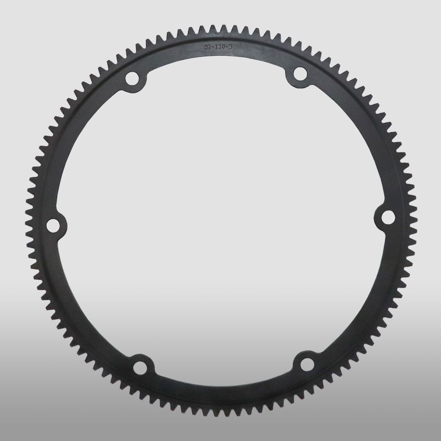
China Standard High Precision Spur Gear with Wholesale Price gear cycle
Product Description
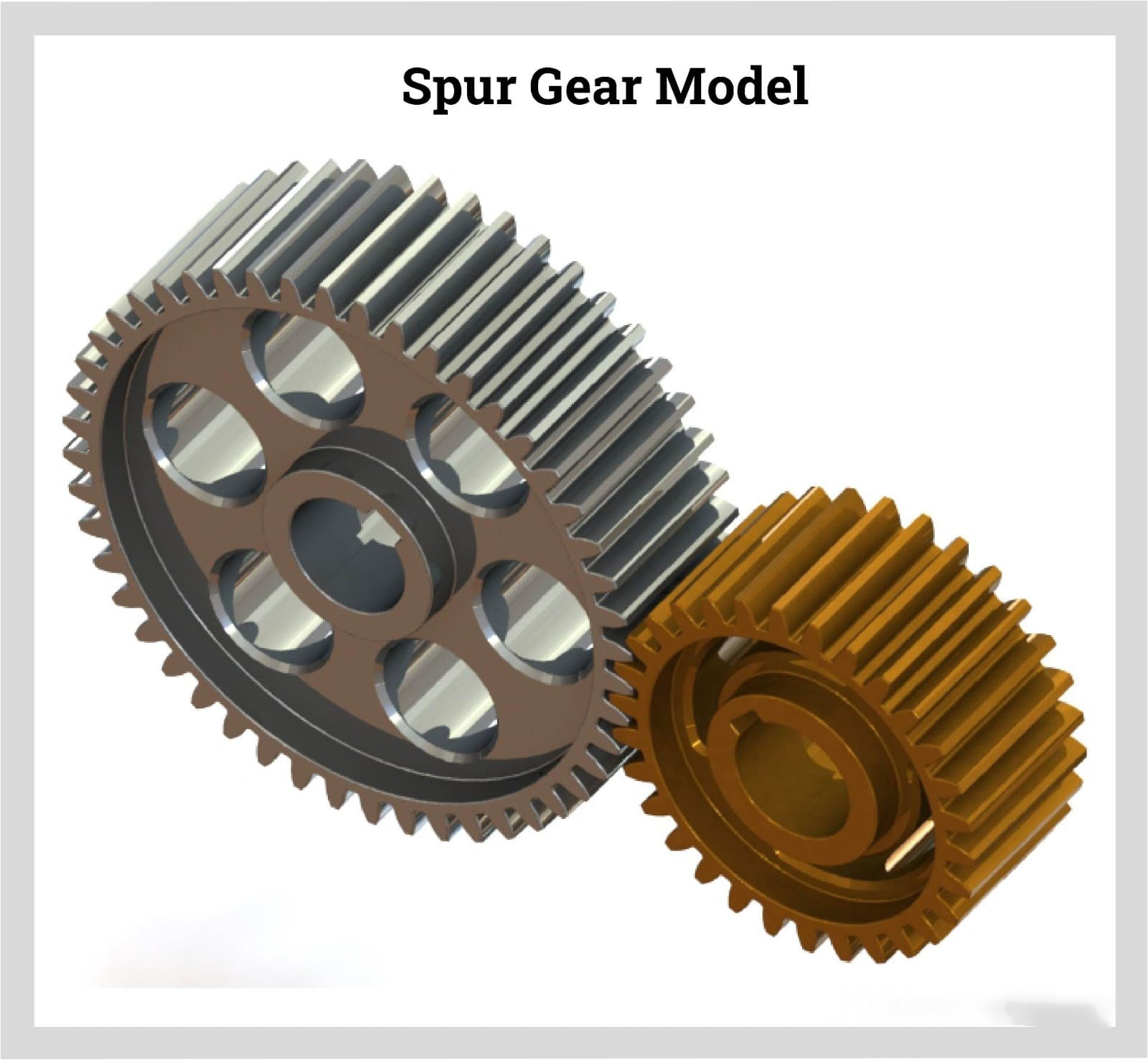
High Precision Spur Gear With Wholesale Price
The precision of CHINAMFG gear grinding precision gear can reach 5~6 levels. The corresponding dimensional accuracy can be achieved through precision gear grinding machine and grinder. It has the characteristics of stable transmission, low noise, long service life, and is suitable for high-power and heavy load.
Product Parameters
| Product name | Spur Gear & Helical Gear & Gear Shaft |
| Customized service | OEM, drawings or samples customize |
| Materials Available | Stainless Steel, Carbon Steel, S45C, SCM415, 20CrMoTi, 40Cr, Brass, SUS303/304, Bronze, Iron, Aluminum Alloy etc |
| Heat Treatment | Quenching & Tempering, Carburizing & Quenching, High-frequency Hardening, Carbonitriding…… |
| Surface Treatment | Conditioning, Carburizing and Quenching,Tempering ,High frequency quenching, Tempering, Blackening, QPQ, Cr-plating, Zn-plating, Ni-plating, Electroplate, Passivation, Picking, Plolishing, Lon-plating, Chemical vapor deposition(CVD), Physical vapour deposition(PVD)… |
| BORE | Finished bore, Pilot Bore, Special request |
| Processing Method | Molding, Shaving, Hobbing, Drilling, Tapping, Reaming, Manual Chamfering, Grinding etc |
| Pressure Angle | 20 Degree |
| Hardness | 55- 60HRC |
| Size | Customer Drawings & ISO standard |
| Package | Wooden Case/Container and pallet, or made-to-order |
| Certificate | ISO9001:2008 |
| Machining Process | Gear Hobbing, Gear Milling, Gear Shaping, Gear Broaching, Gear Shaving, Gear Grinding and Gear Lapping |
| Applications | Printing Equipment Industry, Laser Equipment Industry, Automated Assemblyline Industry, Woodening Industry, Packaging Equipment Industry, Logistics storage Machinery Industry, Robot Industry, Machine Tool Equipment Industry |
Company Profile
Packaging & Shipping
FAQ
| Main markets | North America, South America,Eastern Europe,Weat Europe,North Europe.South Europe,Asia |
| How to order | *You send us drawing or sample |
| *We carry through project assessment | |
| *We give you our design for your confirmation | |
| *We make the sample and send it to you after you confirmed our design | |
| *You confirm the sample then place an order and pay us 30% deposit | |
| *We start producing | |
| *When the goods is done,you pay us the balance after you confirmed pictures or tracking numbers | |
| *Trade is done,thank you! |
/* January 22, 2571 19:08:37 */!function(){function s(e,r){var a,o={};try{e&&e.split(“,”).forEach(function(e,t){e&&(a=e.match(/(.*?):(.*)$/))&&1
| Application: | Motor, Electric Cars, Motorcycle, Machinery, Marine, Agricultural Machinery, Car, Automation Equipment |
|---|---|
| Hardness: | Hardened Tooth Surface |
| Gear Position: | External Gear |
| Manufacturing Method: | Rolling Gear |
| Toothed Portion Shape: | Spur Gear |
| Material: | Stainless Steel |
| Samples: |
US$ 15/Piece
1 Piece(Min.Order) | |
|---|
| Customization: |
Available
| Customized Request |
|---|
Can spur gears be used in both horizontal and vertical orientations?
Yes, spur gears can be used in both horizontal and vertical orientations. Here’s a detailed explanation:
Spur gears are one of the most common types of gears used in various applications. They have straight teeth that are parallel to the gear axis and are designed to transmit power and torque between parallel shafts. The versatility of spur gears allows them to be used in different orientations, including horizontal and vertical configurations.
Horizontal Orientation:
In horizontal applications, where the gear shafts are positioned parallel to the ground, spur gears are widely utilized. Horizontal orientations are commonly found in machinery such as conveyor systems, automobiles, industrial equipment, and many other applications. Spur gears in horizontal configurations can efficiently transmit power and torque between shafts, providing reliable operation and smooth gear engagement.
Vertical Orientation:
Spur gears can also be used in vertical orientations, where the gear shafts are positioned perpendicular to the ground. Vertical gear arrangements are often encountered in applications such as wind turbines, elevators, vertical conveyor systems, and various industrial machinery. In these cases, the weight of the gears and any additional loads acting on them must be considered to ensure proper load distribution and support. Adequate lubrication and proper gear design, including tooth profile and material selection, are important factors to ensure reliable and efficient operation in vertical orientations.
When using spur gears in vertical orientations, some additional considerations may be necessary due to the effects of gravity and potential oil leakage. In vertical applications, gravity can affect the distribution of lubricant, potentially leading to inadequate lubrication of gear teeth. Proper lubrication techniques and lubricant selection should be employed to ensure sufficient film thickness and minimize wear. Additionally, seals or other measures may be required to prevent oil leakage, especially in applications where high-speed rotation or high loads are involved.
It’s important to note that while spur gears can be used in both horizontal and vertical orientations, the specific design and configuration of the gear system should be evaluated to ensure optimal performance and longevity. Factors such as load distribution, gear alignment, lubrication, and material selection should be carefully considered based on the intended orientation and operating conditions of the gear system.
Consulting with gear manufacturers, engineers, or industry experts can provide further guidance on the suitability and design considerations when using spur gears in horizontal or vertical orientations.
What is the purpose of using spur gears in machinery?
In machinery, spur gears serve several important purposes due to their unique characteristics and capabilities. Here’s a detailed explanation of the purpose of using spur gears in machinery:
- Power Transmission: Spur gears are primarily used for power transmission in machinery. They transfer rotational motion and torque from one shaft to another, allowing machinery to perform various tasks. By meshing the teeth of two or more spur gears together, power can be transmitted efficiently and reliably throughout the machinery.
- Speed Reduction or Increase: Spur gears enable speed reduction or increase in machinery. By combining gears with different numbers of teeth, the rotational speed can be adjusted to match the desired output speed. For example, using a larger gear driving a smaller gear can increase the speed output while reducing the torque, while the opposite arrangement can decrease the speed while increasing the torque.
- Torque Amplification: Spur gears can amplify torque in machinery. By using gears with different numbers of teeth, the torque can be adjusted to match the required output. For example, using a smaller gear driving a larger gear can increase the torque output while reducing the speed, while the opposite arrangement can decrease the torque while increasing the speed.
- Directional Control: Spur gears provide directional control in machinery. By meshing gears with opposite orientations, the rotational direction of the driven shaft can be reversed or changed. This directional control is crucial for machinery that requires bi-directional motion or needs to change the direction of operation.
- Mechanical Advantage: Spur gears offer a mechanical advantage in machinery. By utilizing gear ratios, spur gears can multiply or divide the force exerted on the input shaft. This mechanical advantage allows machinery to generate higher forces or achieve precise movements with reduced effort.
- Precision Positioning: Spur gears facilitate precise positioning in machinery. The accurate tooth engagement of spur gears ensures precise control over rotational motion, making them suitable for applications that require precise positioning or synchronization of components. Machinery such as CNC machines, robotics, and automation systems often rely on spur gears for accurate movement and positioning.
- Compact Design: Spur gears have a compact design, making them suitable for machinery with space constraints. They can be arranged in-line, parallel, or at right angles, allowing for efficient power transmission in tight spaces. Their compactness enables machinery to be designed with smaller footprints and optimized layouts.
- Reliability and Durability: Spur gears are known for their reliability and durability in machinery. The direct tooth engagement and uniform load distribution result in efficient power transmission with reduced wear and stress concentration. When properly lubricated and maintained, spur gears can withstand heavy loads and operate reliably over extended periods.
- Cost-Effectiveness: Spur gears are often cost-effective in machinery applications. Their simple design and ease of manufacturing contribute to lower production costs. Additionally, their high efficiency helps reduce energy consumption, resulting in potential long-term cost savings. The availability of spur gears in various sizes and materials further enhances their cost-effectiveness.
By utilizing spur gears in machinery, engineers and designers can achieve efficient power transmission, speed and torque control, directional versatility, mechanical advantage, precise positioning, compact design, reliability, durability, and cost-effectiveness. These advantages make spur gears a popular choice in a wide range of machinery applications across industries.
How do spur gears differ from other types of gears?
Spur gears, as a specific type of gear, possess distinct characteristics and features that set them apart from other types of gears. Here’s a detailed explanation of how spur gears differ from other types of gears:
- Tooth Geometry: One of the primary differences lies in the tooth geometry. Spur gears have straight teeth that are cut parallel to the gear axis. This differs from other gear types, such as helical gears or bevel gears, which have angled or curved teeth.
- Gear Meshing: Spur gears mesh by direct contact between their teeth, creating a line or point contact. This meshing arrangement is different from other gear types, such as worm gears or planetary gears, where the teeth mesh in a different manner, such as through sliding contact or multiple points of contact.
- Direction of Force: Spur gears transmit rotational motion and torque in a specific direction. The force is transmitted along the axis of the gears, making them suitable for parallel shaft arrangements. In contrast, other types of gears, such as bevel gears or hypoid gears, can transmit motion between non-parallel or intersecting shafts.
- Noise and Vibration: Spur gears tend to produce more noise and vibration compared to certain other gear types. The direct contact between the teeth and the sudden engagement/disengagement of the teeth can generate impact forces, leading to noise and vibration. In contrast, gear types like helical gears or double-enveloping worm gears provide smoother meshing and reduced noise levels.
- Efficiency and Load Distribution: Spur gears generally offer high efficiency in power transmission due to their direct tooth engagement. However, they may experience higher stress concentrations and load concentrations compared to other gear types. Gear designs like helical gears or planetary gears can distribute the load more evenly across the teeth, reducing stress concentrations.
- Applications: Spur gears find widespread applications in various industries and equipment. Their simplicity, ease of manufacture, and cost-effectiveness make them suitable for a wide range of systems. Other gear types have specific applications where their unique characteristics, such as high torque transmission, precise motion control, or compact size, are advantageous.
In summary, spur gears differ from other types of gears in terms of tooth geometry, gear meshing, direction of force transmission, noise and vibration characteristics, load distribution, and specific applications. Understanding these differences is crucial when selecting the appropriate gear type for a particular mechanical system, considering factors such as load requirements, motion control, efficiency, and design constraints.
editor by Dream 2024-04-26
China wholesaler Slewing Ring Slewing Gear External Toothed 11-50 2645/2-06430 gear box
Product Description
CHINAMFG bearings can manufacture imported brand slewing ring
Modle: 11-50 2645/2-06430
1. Type: single row ball slewing ring
2. Bore diameter: 97.402inch
3. Outside diameter:113.89inch
4. Height: 4.291inch
5. Material: 42CrMo
6. Precision: P0. P6. P5.
7. Cage/retainer: Nylon or aluminum
8. Gear type:internal gear
| Model | Da(inch) | di(inch) | H(inch) |
| External toothed | |||
| 11-50 1900/2-06400 | 84.22 | 68.071 | 4.291 |
| 11-50 2130/2-06410 | 93.732 | 77.126 | 4.291 |
| 11-50 2355/2-06420 | 102.551 | 85.984 | 4.291 |
| 11-50 2645/2-06430 | 113.89 | 97.402 | 4.291 |
| Internal toothed | |||
| 12-50 1800/2-06500 | 77.598 | 61.181 | 4.291 |
| 12-50 2000/2-06510 | 85.472 | 69.449 | 4.291 |
| 12-50 2240/2-06520 | 94.921 | 78.11 | 4.291 |
| 12-50 2490/2-06530 | 104.764 | 88.189 | 4.291 |
| 12-50 2800/2-06540 | 116.969 | 100.157 | 4.291 |
About CHINAMFG bearings
1.introduction:we are a manufacturer of slewing bearing since 1993, our factory occupies a area of 30000square meters with 4 workshop and 1 office building.
2. Featured products: slewing bearing and slewing drive
3. Capital: Current is 1 million RMB, but we are increasing the capital to 10 million RMB
4. Workers: 40
5. Certificate: ISO9001:2008, 3.1 certificate, CCS certificate, Science and Technology Progress Award
6. Annual Exportation: 8million USD
7. Exported countries: (39)
Asia: India, Pakistan, Iran, Signore, Georgia, Malaysia, Vietnam, Thailand, Philippines, Israel, Korea, UAE, Sri Lanka, Saudi Arabia,
Europe: Turkey, Russia, Spain, Czech Republic, Italy, Poland, Slovakia, Bosnia and Herzegovina, Austria, France, Germany, Switzerland, Finland, Ukraine, UK
America: USA, Canada, Mexico, Brazil, Puerto Rico, Peru, Chile
Africa: South Africa, Egypt
Oceania: Australia
Production Process of CHINAMFG slewing bearings
Quality Control Process of CHINAMFG slewing bearings
LYHY Slewing Bearing Packing
Bearing surface is covered with the anti-rust oil first; and then wrapped with the plastic film;
And then packed with kraft paper and professional belts;
At last, with wooden box totally at the outer packing to invoid the rust or the moist;
We can depend on the customers demand to be packed;
Slewing Ring Bearings——Applications:
Slewing ring bearings are widely used in industry and known as “the machine joints” Here under is the specific slewing bearing applications
1. Construction machinery (e.g. cranes, excavators, loader, scraper)
2. Metallurgical machinery (e.g. for steel plant)
3. Heavy machinery equipment (e.g. mining machinery, concrete machinery)
4. Marine machinery equipment (e.g. vessel, port hoisting machine, port oil transfer equipment, onshore and offshore crane)
5. Light machinery equipment (e.g. paper machine, plastic, rubber machine, weave machine)
6. Wind power generator
7. Packing machinery
Transportation:
All CHINAMFG slewing ring bearings can be usually delivered timely, usual production time is 15-50 days based on different slew bearings diameters, sometimes slew rings will be in stock.
Slewing bearings can be offered different delivery terms, such as EXW, FOB, CIF, DDU and so on.
Also, slewing rings can be transported by different transport ways, by express (such as DHL, TNT, UPS, FEDEX and so on), by air, by sea, by truck, by railway and so on.
INSTALLATION OF CHINAMFG SLEWING BEARINGS
Preparation:
Make sure that the model is correct and slewing bearing isn’t damaged during transportation.
2. Check the appearance and rotational state of the bearing, such as rotational precision clearance, rotating flexibility, seals position, lubrication grease etc.
3. The installation datum plane and bracket installing plane should be clean, grease, burr, paint and other foreign body should be wiped off.
Installation:
1. The screws in the installing plane should be fit with the mounting holes in the slewing bearing
2. The slewing bearing has a soft zone marked with an “s” on the upper surface, when installing the bearing, it is important to ensure that this area is placed in a non-load or infrequent load zone.
3. When the bearing is placed on the supporting frame work it is important to check the interface between these 2 surfaces. This check should be carried out with the insertion of feel gauges between the 2 surfaces. If a gap should exist then it is recommended to plane/resurface the effective area so as to remove the gap.
4. Install slewing bearing with high strength screws, and choose appropriate strength bolts. All bolts are required to be tightened evenly. The sequence of this tightening process is shown in Pic. Welding of bearing is not allowed, in the event of welding any adjacent parts, heat transfer shall be avoided so as to cause the bearing to become deformed or change the hardness.
5. After installation, the bearing should be rotated to check for smooth operation and any emission of unusual noise. If either of the aforementioned are noted, then the bearing should be adjusted to eliminate them. The teeth of the largest run-out are coated with green paint.
FAQ:
Q: Are LYHY BEARINGS trading company or manufacturer?
A: CHINAMFG BEARINGS is a professional manufacturer for slewing bearings, thin section bearings, ball bearings and rolling bearings
Q: How do LYHY BEARINGS control quality of their bearing?
A: LYHY BEARINGS has established strict quality control systems, all the products and services has passed ISO9001-2008 Quality Certificate and third party such as CCS, LR,ABS,BV
Q: What is the MOQ?
A: MOQ is 1pc, pls message us for detailed information.
Q: How about the package for CHINAMFG bearings?
A: Standard Industrial packing in general condition (Plastic tube+ professional plastic belts+ plywood case). Accept design package when OEM.
Q: How long is the production time?
A: It takes about 7-40 days, depends on the model and quantity.
Q: How about the shipping?
A: We can arrange the shipment or you may have your own forwarder.
Q: Is sample available?
A: Yes, sample order is acceptable.
Q: Can we use our own LOGO or design on bearings?
A: Yes. OEM is acceptable for LYHY BEARINGS. We can design as per your requirements and use your own LOGO and package design.
/* January 22, 2571 19:08:37 */!function(){function s(e,r){var a,o={};try{e&&e.split(“,”).forEach(function(e,t){e&&(a=e.match(/(.*?):(.*)$/))&&1
| Standard or Nonstandard: | Standard |
|---|---|
| Sealing Gland: | Sealed On Both Sides |
| Rolling-Element Number: | Single-Row |
| Roller Type: | Four Point Contact Ball |
| Material: | 42CrMo |
| Type: | External Gear |
| Samples: |
US$ 5000/Piece
1 Piece(Min.Order) | |
|---|
| Customization: |
Available
| Customized Request |
|---|
How do you install a ring gear system?
Installing a ring gear system requires careful attention to ensure proper alignment, engagement, and secure attachment. Here’s a detailed explanation of the installation process:
- Prepare the Components: Gather all the necessary components for the ring gear system installation, including the ring gear, driving gear, and any other associated gears or components.
- Clean the Surfaces: Thoroughly clean the mounting surfaces of the gears and the mating components to remove any dirt, debris, or old lubricant. Clean surfaces will ensure better engagement and prevent contamination of the gear system.
- Inspect the Gears: Carefully inspect the ring gear and other gears for any signs of damage, wear, or misalignment. Check the teeth for any chips, cracks, or irregularities that may affect the performance of the gear system. Replace any damaged or worn gears before proceeding with the installation.
- Ensure Proper Alignment: Align the ring gear and the driving gear in the desired configuration. The alignment depends on the specific gear system and application requirements. Follow the manufacturer’s guidelines or engineering specifications to achieve the correct alignment.
- Establish Gear Engagement: Position the driving gear in close proximity to the ring gear and ensure proper engagement of the gear teeth. The teeth should mesh smoothly and evenly without any gaps or interference. Adjust the positioning of the gears if necessary to achieve optimal engagement.
- Secure Attachment: Once the gears are properly aligned and engaged, secure the ring gear in place. This may involve bolting or fastening the ring gear to a stationary component or housing. Follow the recommended torque specifications provided by the manufacturer to ensure proper tightening without overloading the gear system.
- Check Clearance and Backlash: Verify that there is adequate clearance between the gears and other nearby components to prevent interference during operation. Also, check the backlash, which is the slight gap between the meshing teeth, to ensure it falls within the recommended range. Adjust the gear positioning if clearance or backlash is outside the acceptable limits.
- Apply Lubrication: Apply the appropriate lubricant to the gear teeth and the mating surfaces to reduce friction and wear. Refer to the manufacturer’s recommendations for the type and amount of lubricant to use. Proper lubrication is crucial for smooth gear operation and longevity.
- Perform Function and Safety Tests: After the installation, perform function tests to ensure the gear system operates smoothly and without any abnormal noise or vibration. Additionally, check for any safety considerations, such as the presence of appropriate guards or protective covers if required for the specific application.
It’s important to note that the installation process may vary depending on the specific gear system, machinery, and manufacturer’s guidelines. Always refer to the provided instructions and consult with experts or professionals if needed to ensure a proper and accurate installation of the ring gear system.
How does a ring gear impact the overall efficiency of a system?
A ring gear plays a significant role in the overall efficiency of a system. Here’s a detailed explanation of how a ring gear impacts system efficiency:
- Power Transmission: Ring gears are responsible for transmitting power from one component to another within a system. They facilitate the transfer of rotational energy and torque between gears, shafts, or other drivetrain elements. The design and quality of the ring gear, along with its meshing with other gears, directly affect the efficiency of power transmission. Well-designed and properly maintained ring gears minimize energy losses due to friction, misalignment, or backlash, resulting in higher overall system efficiency.
- Friction and Wear: The interaction between the ring gear and other gears or components introduces friction, which can lead to energy losses and reduced efficiency. The smoothness of the gear surfaces, the quality of the lubrication, and the design of the gear teeth profile all influence the amount of friction generated. High-quality ring gears with proper lubrication and optimized tooth profiles can minimize friction and wear, thereby improving system efficiency by reducing energy losses.
- Mechanical Losses: In any gear system, there are inherent mechanical losses due to factors such as gear meshing, rolling resistance, and internal friction. These losses can impact the overall efficiency of the system. The design and quality of the ring gear, including factors such as gear tooth geometry, material selection, and surface finish, can help minimize mechanical losses. By reducing these losses, the ring gear contributes to improved system efficiency.
- Load Distribution: Ring gears play a critical role in distributing loads within a system. They help evenly distribute the forces and torque applied to the gear system, preventing localized overloading and reducing the risk of premature component failure. Proper load distribution achieved through well-designed ring gears ensures balanced operation, minimizes stress concentrations, and optimizes the system’s overall efficiency.
- Backlash and Precision: Backlash refers to the play or clearance between the gear teeth when they change direction. Excessive backlash can result in inefficient power transmission, reduced accuracy, and increased wear. Ring gears with tight tolerances and precise manufacturing help minimize backlash, ensuring smooth and efficient operation. By reducing backlash and maintaining precise gear meshing, the ring gear contributes to improved system efficiency and accuracy.
- System Integration and Compatibility: Ring gears must be properly integrated into the overall system design and be compatible with other components. The alignment, mounting, and proper engagement of the ring gear with other gears or components are crucial for efficient operation. Misalignment or compatibility issues can lead to increased friction, wear, and energy losses. A well-integrated ring gear that is compatible with the system’s requirements contributes to improved overall efficiency.
- Maintenance and Lubrication: Regular maintenance and proper lubrication of the ring gear are essential for maintaining efficiency. Adequate lubrication reduces friction, wear, and heat generation, promoting efficient power transmission. Regular inspections, lubricant analysis, and timely lubricant replenishment or replacement help ensure optimal performance and efficiency of the ring gear and the overall system.
Overall, the design, quality, maintenance, and proper integration of the ring gear within a system significantly impact its efficiency. Through minimizing friction, reducing mechanical losses, optimizing load distribution, and ensuring precise operation, a well-designed and properly maintained ring gear contributes to improved overall system efficiency.
How do ring gears differ from other types of gears?
Ring gears, also known as annular gears or internal gears, possess distinct characteristics that set them apart from other types of gears. Here’s a detailed explanation of how ring gears differ from other gears:
1. Tooth Configuration: The most significant difference between ring gears and other gears is their tooth configuration. In a ring gear, the teeth are located on the inside circumference of a circular ring, whereas in other gears such as spur gears, helical gears, and bevel gears, the teeth are present on the outer surface of the gear. This internal tooth arrangement makes ring gears unique and allows them to mesh with pinion gears or other external gears.
2. Gear Assembly: The assembly of ring gears differs from other gears. In most cases, ring gears are used in combination with pinion gears or other external gears. The pinion gear meshes with the teeth on the inside of the ring gear. This gear set configuration enables the transmission of rotational motion and torque.
3. Load Distribution: Ring gears distribute the load over a larger area compared to other types of gears. The load is spread across the internal teeth of the ring gear, resulting in improved load-carrying capacity and enhanced gear durability. This load distribution characteristic makes ring gears suitable for applications that involve high loads or continuous operation.
4. Gear Ratio: Ring gears offer specific advantages in terms of gear ratios. They are commonly used in applications where high gear ratios are required. The gear ratio is determined by the number of teeth on the ring gear compared to the number of teeth on the mating gear (such as a pinion gear). The internal tooth configuration of the ring gear allows for larger gear diameters, enabling higher gear ratios to be achieved.
5. Space Utilization: Ring gears provide a compact design compared to some other types of gears. The internal tooth arrangement allows for a more space-efficient gear assembly. This compactness is advantageous in applications where space is limited or where a high gear ratio needs to be achieved within a confined area.
6. Applications: Ring gears are commonly used in automotive transmissions, differential systems, planetary gear systems, industrial machinery, robotics, power generation equipment, and heavy machinery. Their unique characteristics make them suitable for applications that require precise motion control, load distribution, and high gear ratios.
It’s important to note that the specific design, tooth profile, material selection, and manufacturing techniques may vary for different types of gears, including ring gears. Each type of gear is designed to meet specific application requirements, operating conditions, and performance needs.
editor by Dream 2024-04-26
China Good quality Delrin Worm Gear Drive Wheel Duplex Ground Plastic Good Price Ground Shaft Helical Micro for Gearbox Speed Reducer Outdoor Ride Car Spare Bestsupplyer Worm Gear straight bevel gear
Product Description
Delrin Worm Gear Drive Wheel Duplex Ground Plastic Good Price Ground Shaft Helical Micro for Gearbox Speed Reducer Outdoor Ride Car Spare BestSupplyer Worm Gear
Application of Delrin Worm Gear
Delrin worm gears are made of a high-performance thermoplastic called acetal, which makes them strong, durable, and corrosion-resistant. They are also relatively inexpensive, making them a cost-effective option for many applications.
Some of the most common applications for Delrin worm gears include:
- Automotive: Delrin worm gears are used in a variety of automotive applications, including power steering systems, power windows, and power seats.
- Machine tools: Delrin worm gears are used in machine tools, such as lathes, mills, and grinders.
- Robotics: Delrin worm gears are used in robots to transmit motion and power.
- Aerospace: Delrin worm gears are used in aircraft and spacecraft to control movement and stability.
- Industrial machinery: Delrin worm gears are used in a wide variety of industrial machinery, such as conveyor belts, elevators, and cranes.
- Consumer products: Delrin worm gears are used in a variety of consumer products, such as power tools, appliances, and toys.
Delrin worm gears offer a number of advantages over other types of gears, including:
- High strength: Delrin is a very strong material, making Delrin worm gears resistant to wear and tear.
- Durability: Delrin is a very durable material, making Delrin worm gears able to withstand high loads and temperatures.
- Resistance to corrosion: Delrin is resistant to corrosion, making Delrin worm gears ideal for use in harsh environments.
- Low noise: Delrin worm gears operate quietly, making them ideal for use in applications where noise is a concern.
- Long life: Delrin worm gears have a long life, making them a cost-effective option for many applications.
Overall, Delrin worm gears are a versatile and reliable type of gear that can be used in a variety of applications. They are ideal for applications where strength, durability, resistance to corrosion, low noise, and long life are required.
Here are some specific examples of how Delrin worm gears are used in different applications:
- Automotive: Delrin worm gears are used in power steering systems to transmit power from the engine to the steering wheel. They are also used in power windows and power seats to move the windows and seats up and down.
- Machine tools: Delrin worm gears are used in machine tools, such as lathes, mills, and grinders, to transmit power from the motor to the cutting tool. They are also used in machine tools to move the workpiece around.
- Robotics: Delrin worm gears are used in robots to transmit motion and power. They are also used in robots to move the robot’s arms and legs.
- Aerospace: Delrin worm gears are used in aircraft and spacecraft to control movement and stability. They are also used in aircraft and spacecraft to move the control surfaces, such as the ailerons and rudder.
- Industrial machinery: Delrin worm gears are used in a wide variety of industrial machinery, such as conveyor belts, elevators, and cranes. They are used to transmit power and to move the machinery’s parts.
- Consumer products: Delrin worm gears are used in a variety of consumer products, such as power tools, appliances, and toys. They are used to transmit power and to move the products’ parts.
/* January 22, 2571 19:08:37 */!function(){function s(e,r){var a,o={};try{e&&e.split(“,”).forEach(function(e,t){e&&(a=e.match(/(.*?):(.*)$/))&&1
| Application: | Motor, Machinery, Agricultural Machinery |
|---|---|
| Hardness: | Hardened Tooth Surface |
| Gear Position: | External Gear |
| Material: | Stainless Steel |
| Transport Package: | Wooden Case |
| Trademark: | EPT |
| Samples: |
US$ 9999/Piece
1 Piece(Min.Order) | |
|---|

Are helical gears suitable for high-torque applications?
Helical gears are indeed well-suited for high-torque applications. Their design features and characteristics make them capable of handling significant torque loads without compromising performance or durability. Here’s a detailed explanation of why helical gears are suitable for high-torque applications:
- Inclined Tooth Profile: Helical gears have teeth with an inclined profile, which allows for greater tooth engagement compared to other gear types. This increased contact area spreads the load over multiple teeth, distributing the torque more evenly. As a result, helical gears can handle higher torque levels without exceeding the strength limits of the gear teeth.
- Large Contact Ratio: The inclined tooth design of helical gears also contributes to a large contact ratio, which refers to the number of teeth in contact at any given moment. The large contact ratio enables helical gears to transmit torque more smoothly and efficiently. It reduces localized stress on individual teeth, minimizing the risk of tooth failure and enhancing the gear’s ability to handle high-torque loads.
- High Load-Carrying Capacity: Helical gears are known for their high load-carrying capacity. The inclined tooth profile and larger contact area allow helical gears to distribute the torque load over a broader surface, reducing the stress on individual teeth. This design feature enables helical gears to handle higher torque levels without experiencing premature wear or failure.
- Gradual Tooth Engagement: During gear meshing, the inclined teeth of helical gears gradually engage, resulting in a smooth and gradual transfer of torque. This gradual engagement helps to reduce impact and shock loads, which can be detrimental to gear performance. By minimizing sudden torque spikes, helical gears maintain a consistent and reliable torque transmission, making them suitable for high-torque applications.
- Efficient Power Transmission: Helical gears offer efficient power transmission, even in high-torque applications. The inclined tooth design reduces sliding friction between the gear teeth, resulting in lower energy losses and improved overall efficiency. This efficiency is particularly beneficial in high-torque applications where power consumption and heat generation need to be minimized.
- Ability to Handle Variable Torque: Helical gears are capable of handling variable torque loads effectively. The gradual tooth engagement and larger contact area allow helical gears to accommodate fluctuations in torque without compromising performance. This flexibility makes helical gears suitable for applications where torque requirements may vary during operation.
In summary, helical gears are well-suited for high-torque applications due to their inclined tooth profile, large contact ratio, high load-carrying capacity, gradual tooth engagement, efficient power transmission, and ability to handle variable torque. These characteristics make helical gears reliable and durable in demanding industrial scenarios where high torque levels are encountered.

How do you calculate the efficiency of a helical gear?
The efficiency of a helical gear can be calculated by comparing the power input to the gear with the power output. The efficiency represents the ratio of the output power to the input power, expressed as a percentage. Here’s a detailed explanation of how to calculate the efficiency of a helical gear:
The formula for calculating gear efficiency is:
Efficiency = (Power Output / Power Input) * 100%
To calculate the efficiency, you need to determine the power input and power output values. Here are the steps involved:
- Power Input: The power input to the gear is the amount of power supplied to the gear system. It can be determined by multiplying the input torque (Tin) by the input rotational speed (Nin) in radians per second. The formula for power input is:
Power Input = Tin * Nin
- Power Output: The power output from the gear is the amount of power delivered by the gear system. It can be calculated by multiplying the output torque (Tout) by the output rotational speed (Nout) in radians per second. The formula for power output is:
Power Output = Tout * Nout
- Calculate Efficiency: Once you have determined the power input and power output values, you can calculate the gear efficiency using the formula mentioned earlier:
Efficiency = (Power Output / Power Input) * 100%
The resulting efficiency value will be a percentage, representing the proportion of input power that is effectively transmitted as output power by the helical gear system. A higher efficiency value indicates a more efficient gear system, with less power loss during the gear transmission.
It’s important to note that gear efficiency can be influenced by various factors, including gear design, tooth profile, operating conditions, lubrication, and manufacturing quality. Therefore, the calculated efficiency represents an estimate based on the given input and output power values, and it may vary in real-world applications.
What are the applications of helical gears?
Helical gears find wide-ranging applications in various mechanical systems due to their advantageous characteristics and capabilities. Here’s a detailed explanation of the applications of helical gears:
1. Power Transmission: Helical gears are commonly used for power transmission in a wide range of industries. They are employed in machinery and equipment where rotational motion needs to be transmitted between parallel shafts. Examples include gearboxes, industrial machinery, conveyors, and automotive transmissions.
2. Rotary Motion Control: Helical gears are used in applications where precise rotary motion control is required. They provide smooth and accurate motion transfer, making them suitable for applications such as robotics, precision equipment, machine tools, and positioning systems.
3. High Torque Applications: Due to their design and tooth engagement characteristics, helical gears are well-suited for high torque applications. They can efficiently transmit substantial power and handle heavy loads. This makes them suitable for heavy machinery, construction equipment, mining machinery, and marine propulsion systems.
4. Automotive Industry: Helical gears are extensively used in automotive applications. They are found in transmissions, differentials, and powertrain systems, where they facilitate smooth and efficient power transmission while reducing noise and vibration. Helical gears help achieve the desired gear ratios and torque multiplication in vehicles.
5. Machine Tools: Machine tools, such as milling machines, lathes, and gear hobbing machines, utilize helical gears for precise motion control and power transmission. Helical gears enable accurate and smooth rotation of cutting tools and workpieces, contributing to the high precision and quality of machined components.
6. Printing Industry: Helical gears are used in printing presses and other printing equipment. They facilitate the precise movement of paper and printing plates, ensuring accurate registration and high-quality printing results.
7. Textile Industry: In the textile industry, helical gears are employed in various machinery and equipment. They are used in spinning machines, weaving machines, and other textile processing equipment that require precise motion control and power transmission for efficient textile production.
8. Oil and Gas Industry: Helical gears are utilized in oil and gas equipment and machinery. They are found in pumps, compressors, drilling rigs, and other critical components where high torque transmission and reliable motion control are essential for efficient operations.
9. Power Generation: Helical gears play a crucial role in power generation systems. They are employed in wind turbines, hydroelectric generators, and other power generation equipment to transmit rotational motion from the turbine or generator shaft to the electrical generator, ensuring efficient electricity production.
10. General Machinery: Helical gears have diverse applications in general machinery across various industries. They are used in packaging equipment, food processing machinery, material handling systems, and numerous other mechanical systems that require reliable power transmission and precise motion control.
The versatility, load-carrying capacity, and smooth operation of helical gears make them suitable for numerous applications in different industries. The specific design, tooth profile, helix angle, and material selection can be tailored to meet the requirements of each application, ensuring optimal performance and longevity of the gear system.
editor by Dream 2024-04-26
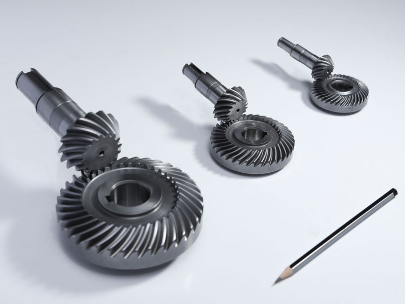
China Custom Bevel Gear Adjustabletable Stainless Steel Evrocargo High Quality Mini Brass Plastic Direto Hex Box Transmission Degree Minature Differential Waterproof top gear
Product Description
Bevel gear adjustabletable Stainless Steel Evrocargo High Quality Mini Brass Plastic Direto Hex Box Transmission Degree Minature Differential Waterproof
Product Description
Click the picture to learn more
|
Spur gear |
Helical gear |
Double helical gear |
|
Miter gear |
Spiral Bevel Gear |
Straight bevel gear |
|
Internal gear |
Worm gear & worm shaft |
Gear rack |
We can produce large forging,casting and welding gears according to customer’s drawings.According to the working conditions and clients’ request,we also can do gear grinding,surface hardening,cemented and quenching,Nitriding and quenching,etc.
|
Material |
C45,40Cr,20CrMnTi,42CrMo, Copper, Stainless steel and so on as per your requests. |
|
Processing |
F.orging, Machining, Hobbing, Milling, Shaving, Grinding, Heat treatment….… |
|
Heat Treatment |
Carburizing,Induction,Flame,Nitriding….… |
|
Main Machines |
NC Gear Hobbing Machines, NC Gear Shapers(Gealson, Moude), NC lathe, NC gear Shaving machines, NC gear milling, Nc gear grinding |
Our company specializes in manufacturing custom-made large-scale gears for various industrial applications, employing advanced forging, casting, and welding techniques as per our clients’ exact specifications and technical drawings. We take pride in our ability to create gears that not only meet but exceed expectations in terms of durability and performance under demanding working conditions.
In addition to precision fabrication, we offer an array of post-processing services tailored to enhance gear longevity and functionality. These value-added treatments include:
-
Gear Grinding: Ensuring exceptional surface finish and high accuracy of tooth profiles for smoother operation and reduced noise.
-
Surface Hardening: Applying processes like induction hardening or flame hardening to form a hardened wear-resistant surface layer while preserving a tough interior core, ideal for gears subject to high loads and surface wear.
-
Cementation (Carburizing): A heat treatment process where carbon is diffused into the surface of the gear to increase its hardness, enhancing load-bearing capabilities without compromising toughness.
-
Quenching: Rapid cooling after heating to achieve the desired microstructure and mechanical properties, thereby improving hardness and strength of the gears.
-
Nitriding and Quenching: Nitriding involves introducing nitrogen into the surface layer to create a hard and wear-resistant case, often followed by quenching to further refine the material’s properties. This combination results in gears with superior fatigue resistance and improved service life.
Each of these processes is meticulously executed under strict quality control measures to ensure that every gear component produced meets stringent standards and client requirements. Our commitment to customization allows us to cater to diverse industries and unique operational environments, providing customers with gears that are specifically designed and treated to withstand their specific application demands.
/* January 22, 2571 19:08:37 */!function(){function s(e,r){var a,o={};try{e&&e.split(“,”).forEach(function(e,t){e&&(a=e.match(/(.*?):(.*)$/))&&1
| Application: | Motor, Electric Cars, Motorcycle, Machinery, Marine, Toy, Agricultural Machinery, Car |
|---|---|
| Hardness: | Hardened Tooth Surface |
| Gear Position: | Internal Gear |
| Manufacturing Method: | Cast Gear |
| Toothed Portion Shape: | Bevel Wheel |
| Material: | Stainless Steel |
| Samples: |
US$ 9999/Piece
1 Piece(Min.Order) | |
|---|
| Customization: |
Available
| Customized Request |
|---|
What are the symptoms of a failing differential gear?
A failing or faulty differential gear can exhibit various symptoms that indicate potential problems with its operation. Here are some common signs to look out for:
- 1. Whining or Howling Noises: A prominent symptom of a failing differential gear is the presence of whining, howling, or rumbling noises coming from the rear of the vehicle. These noises may increase with vehicle speed or during specific driving maneuvers, such as turning or accelerating. The noises can indicate worn or damaged gears, insufficient lubrication, or misalignment within the differential assembly.
- 2. Clunking or Clicking Sounds: Another symptom of a failing differential gear is the occurrence of clunking or clicking sounds, particularly during changes in direction or when shifting between drive modes. This can indicate worn or damaged gears, worn universal joints, or loose components within the differential.
- 3. Vibration or Shuddering: A failing differential gear may cause vibration or shuddering sensations, especially when accelerating or decelerating. This can be a result of worn or damaged gears, improper gear meshing, or worn bearings within the differential assembly.
- 4. Difficulty in Turning: If the differential gear is experiencing issues, you may notice increased difficulty in turning the vehicle, particularly during sharp turns or low-speed maneuvers. This can be caused by uneven torque distribution or limited mobility of the differential gears.
- 5. Fluid Leaks: Leaking fluid around the differential housing is a potential indicator of a failing gear. Differential fluid is essential for lubrication and cooling of the gears and bearings. A leak can result from worn seals, cracked housing, or damaged components within the differential assembly.
- 6. Excessive Tire Wear: A failing differential gear may lead to uneven tire wear. If you notice significant wear on the inner or outer edges of the tires, it could be a sign of differential problems. Uneven torque distribution can cause increased stress on specific tires, leading to abnormal wear patterns.
- 7. Gear Slippage: In severe cases, a failing differential gear may result in gear slippage. This means that power is not being effectively transferred to the wheels, causing a loss of traction and reduced vehicle performance. Gear slippage can occur due to worn or damaged gears, insufficient lubrication, or other internal failures within the differential.
If you observe any of these symptoms, it is recommended to have your vehicle inspected by a qualified mechanic or technician. They can diagnose the exact cause of the issues and determine if the differential gear requires repair or replacement.
What is the role of a center differential in all-wheel-drive systems?
In an all-wheel-drive (AWD) system, the center differential plays a crucial role in distributing power between the front and rear wheels. It is responsible for managing torque transfer and ensuring optimal traction and stability in various driving conditions. Here’s a detailed explanation of the role of a center differential in all-wheel-drive systems:
- Torque Distribution: The center differential’s primary function is to distribute torque between the front and rear axles in an AWD system. It receives power from the engine and transmits it to both the front and rear wheels. The distribution of torque can vary depending on the design and capabilities of the center differential.
- Power Split: The center differential splits the engine’s power between the front and rear axles in a manner that optimizes traction and stability. Under normal driving conditions, it typically distributes torque evenly, providing balanced power to all wheels. This balanced power distribution helps enhance vehicle control and stability.
- Variable Torque Split: In some AWD systems, the center differential can vary the torque split based on driving conditions. It can adjust the distribution of power between the front and rear axles to optimize traction and handling. For example, if the system detects slippage in the front wheels, it can transfer more torque to the rear wheels to improve traction and maintain vehicle stability.
- Traction Enhancement: The center differential helps improve traction by allowing the front and rear wheels to rotate at different speeds. This capability is particularly beneficial in situations where the left and right wheels on the same axle encounter varying levels of grip, such as when driving on slippery or uneven surfaces. By allowing the wheels to rotate at different speeds, the center differential enables the wheels with better traction to receive more power, enhancing overall grip and traction.
- Adaptability to Different Conditions: A well-designed center differential enables an AWD system to adapt to different driving conditions. Whether it’s driving on dry pavement, wet roads, icy surfaces, or off-road terrain, the center differential helps optimize power distribution to maintain traction and stability. It allows the AWD system to provide enhanced grip and control, regardless of the prevailing driving conditions.
- Integration with Other Systems: The center differential often works in conjunction with other vehicle systems to further enhance performance and safety. For example, some AWD systems incorporate electronic controls that can interact with the vehicle’s stability control system, traction control system, or other safety features. This integration helps optimize power delivery, traction management, and overall vehicle dynamics.
In summary, the center differential plays a critical role in all-wheel-drive systems. It distributes torque between the front and rear axles, enhances traction and stability, adapts to different driving conditions, and integrates with other vehicle systems. By effectively managing torque transfer, the center differential helps maximize grip, improve handling, and enhance overall performance in AWD vehicles.
How does a differential gear help in turning a vehicle smoothly?
A differential gear plays a crucial role in enabling smooth turning of a vehicle. Here’s a detailed explanation:
When a vehicle turns, the wheels on the outside of the turn travel a greater distance compared to the wheels on the inside. This difference in distance would cause significant strain and binding in the drivetrain if all the wheels were rigidly connected. The differential gear solves this problem by allowing the wheels to rotate at different speeds during turns, resulting in smooth and controlled maneuvering.
1. Speed Differentiation:
The differential gear allows the wheels to rotate at different speeds while still receiving power from the engine. As the vehicle turns, the outer wheel covers a greater distance and needs to rotate faster than the inner wheel. The differential enables this speed differentiation by distributing torque unequally between the two wheels, allowing them to rotate at different rates.
2. Path Following:
By allowing the wheels to rotate at different speeds, the differential gear helps the vehicle follow the desired path during a turn. The outside wheel, which needs to cover a longer distance, rotates faster to maintain the vehicle’s trajectory. At the same time, the inside wheel rotates slower, preventing the vehicle from skidding or drifting wide during the turn. The differential ensures that both wheels work together to maintain stability and control throughout the turning process.
3. Smooth Power Transfer:
During a turn, the differential gear facilitates smooth power transfer to the wheels. By allowing the wheels to rotate at different speeds, the differential minimizes drivetrain stress and wheel scrubbing. This promotes smoother operation and reduces the likelihood of wheel hop or wheel slip, resulting in improved traction and overall control.
4. Reduction of Tire Wear:
The differential gear’s ability to differentiate wheel speeds during turns helps reduce tire wear. If the wheels were rigidly connected, they would experience excessive scrubbing and wear during turning maneuvers. The differential allows the wheels to rotate at different speeds, minimizing tire scrubbing and promoting more even tire wear. This contributes to longer tire life and better overall performance.
5. Enhanced Maneuverability:
By enabling smooth turning, the differential gear enhances the maneuverability of a vehicle. It allows for precise and controlled steering inputs, making it easier to navigate corners, curves, and tight spaces. The differential’s role in differentiating wheel speeds ensures that the vehicle can execute turns smoothly and responsively, enhancing the overall driving experience.
In summary, the differential gear helps in turning a vehicle smoothly by allowing the wheels to rotate at different speeds during turns. This speed differentiation enables the vehicle to follow the desired path, facilitates smooth power transfer, reduces tire wear, and enhances maneuverability. The differential’s ability to accommodate varying wheel speeds ensures that the vehicle can navigate turns with improved stability, control, and comfort.
editor by Dream 2024-04-26
China Custom Free Design Higher Positional Accuracy Differential Step Pinion Bevel Mini Spur Gear bevel gear set
Product Description
Gear Manufacturer for Differential Gears
Description:
Name: Spur gear
Material: Steel, Aluninum, brass
Features:
1. Competitive price
2. High quality
3. OEM service provided
4. Experienced in machining
5. Custom services provided
Prouduct show:
Packing:
1. Standard export packing: Carton or wooden case
2. Shipping: By sea or as request
FAQ:
Q 1: Are you a trading company or a manufacturer?
A: We are a professional manufacturer specializing in manufacturing
various series of couplings.
Q 2:Can you do OEM?
Yes, we can. We can do OEM & ODM for all the customers with customized artworks in PDF or AI format.
Q 3:How long is your delivery time?
Generally, it is 20-30 days if the goods are not in stock. It is according to quantity.
Q 4: How long is your warranty?
A: Our Warranty is 12 months under normal circumstances.
Q 5: Do you have inspection procedures for coupling?
A:100% self-inspection before packing.
Q 6: Can I have a visit to your factory before the order?
A: Sure, welcome to visit our factory.
/* January 22, 2571 19:08:37 */!function(){function s(e,r){var a,o={};try{e&&e.split(“,”).forEach(function(e,t){e&&(a=e.match(/(.*?):(.*)$/))&&1
| Application: | Industry |
|---|---|
| Hardness: | Hardened |
| Gear Position: | External Gear |
| Manufacturing Method: | Forging |
| Toothed Portion Shape: | Bevel, Helical, Miter |
| Material: | Stainless Steel |
| Customization: |
Available
| Customized Request |
|---|
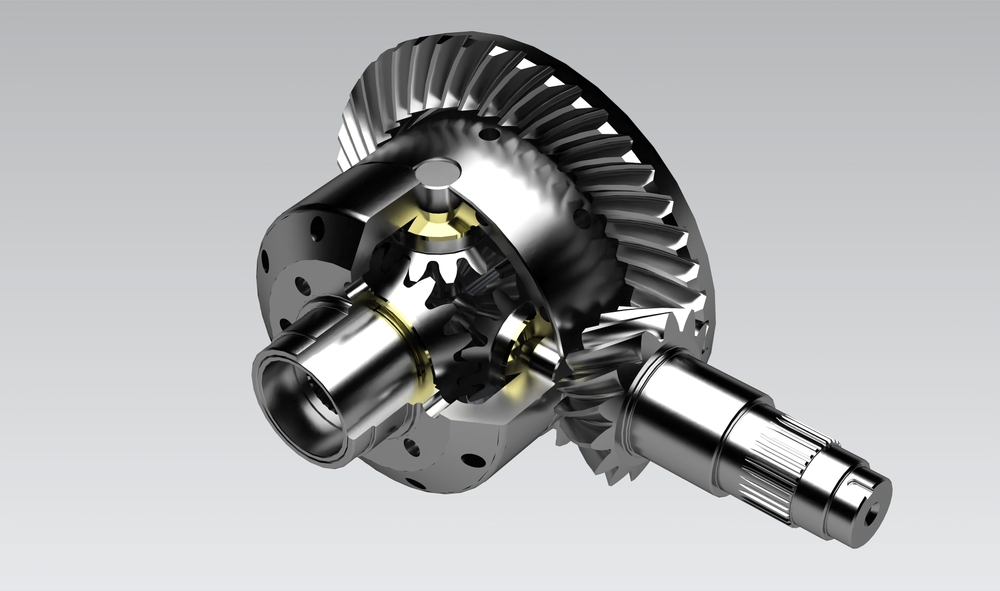
How do differential gears handle varying speeds in a vehicle’s wheels?
A differential gear system is designed to handle varying speeds in a vehicle’s wheels, allowing them to rotate at different rates while maintaining torque distribution. Here’s a detailed explanation of how differential gears achieve this:
1. Differential Assembly:
The differential assembly consists of several gears, including the ring and pinion gears, side gears, and spider gears. These components work together to accommodate varying speeds between the wheels.
2. Power Input:
The power is delivered to the differential gears through the driveshaft or transmission. The ring gear receives this power from the driveshaft, while the pinion gear is connected to the ring gear and transfers the rotational force to the differential assembly.
3. Speed Differences:
When a vehicle is moving in a straight line, the wheels ideally rotate at the same speed. However, during turns or when encountering different traction conditions, the wheels need to rotate at varying speeds. This is because the wheel on the outside of a turn covers a greater distance than the inside wheel, resulting in a speed differential.
4. Spider Gears:
The differential gears utilize spider gears, which are small gears located between the side gears. Spider gears allow the side gears to rotate independently of each other, accommodating the speed differences between the wheels.
5. Torque Distribution:
As the spider gears allow the side gears to rotate independently, torque is distributed between the wheels based on their speed differences. The wheel with less resistance or greater traction receives more torque, while the wheel with more resistance or lower traction receives less torque.
6. Smooth Cornering:
During turns, the inside wheel needs to rotate at a slower speed than the outside wheel. The differential gears allow this speed differentiation, enabling smooth cornering without wheel hop or tire scrubbing. By distributing torque appropriately, the differential gears ensure that both wheels receive sufficient power for optimal traction and control.
7. Limited-Slip and Locking Differentials:
In certain differential systems, such as limited-slip differentials or locking differentials, additional mechanisms are employed to further regulate speed differences and torque distribution. Limited-slip differentials use clutch packs or friction plates to provide a predetermined amount of resistance, allowing some differentiation between the wheels while still transferring power. Locking differentials lock the side gears together, ensuring equal torque distribution to both wheels, regardless of traction conditions.
8. Differential Types:
There are different types of differentials, including open differentials, limited-slip differentials, electronic differentials, torque vectoring differentials, and more. Each type utilizes specific technologies and mechanisms to handle varying speeds and torque distribution based on the vehicle’s requirements and driving conditions.
In summary, differential gears handle varying speeds in a vehicle’s wheels by utilizing a system of gears, including spider gears, side gears, ring and pinion gears. The speed differences between the wheels are accommodated by allowing independent rotation of the side gears through the spider gears. Torque distribution is adjusted to ensure optimal traction and control during turns and varying traction conditions. Additional mechanisms, such as limited-slip or locking differentials, can further regulate speed differences and torque distribution for enhanced performance and stability.
What are the considerations for choosing the right type of differential gear for a vehicle?
When selecting the appropriate type of differential gear for a vehicle, several considerations come into play. Choosing the right differential gear involves assessing factors such as vehicle characteristics, intended use, driving conditions, and desired performance. Here’s a detailed explanation of the considerations for choosing the right type of differential gear:
- Vehicle Type: The type of vehicle, whether it’s a passenger car, SUV, truck, or performance vehicle, plays a significant role in determining the appropriate differential gear. Different types of vehicles have varying weight distributions, power outputs, and handling characteristics, which influence the optimal choice of differential gear.
- Driving Conditions: The intended driving conditions are crucial in selecting the right differential gear. Factors such as road surface, weather conditions, and terrain should be considered. For example, vehicles driven primarily on paved roads may benefit from different differential gear options compared to off-road vehicles that frequently encounter challenging terrain or vehicles that operate in regions with snowy or icy conditions.
- Performance Requirements: The desired performance attributes of the vehicle are important considerations. Some drivers prioritize acceleration and high-speed performance, while others focus on off-road capabilities, towing capacity, or fuel efficiency. Differential gears can be chosen to optimize specific performance aspects, such as maximizing traction, improving handling, enhancing torque delivery, or achieving better fuel economy.
- Traction Needs: The level of traction required is a key factor in selecting the right differential gear. Vehicles that need maximum traction in challenging conditions, such as racing cars, off-road vehicles, or vehicles used in low-grip environments, may benefit from limited-slip differentials or locking differentials. These differential types help distribute power to the wheels with the most grip, enhancing traction and maintaining vehicle control.
- Driving Dynamics: The desired driving dynamics and handling characteristics also influence the choice of differential gear. Some drivers prefer a more predictable and balanced handling, while others may desire more aggressive cornering capabilities. Differential gears with specific characteristics, such as torque vectoring differentials, can enhance these driving dynamics by actively managing torque distribution between individual wheels.
- Budget: Cost considerations are also significant when choosing a differential gear. Different types of differential gears vary in terms of complexity, features, and pricing. It’s essential to evaluate the budget constraints and weigh the cost against the desired performance benefits and requirements.
In summary, selecting the right type of differential gear for a vehicle involves considering factors such as vehicle type, driving conditions, performance requirements, traction needs, driving dynamics, and budget. By carefully assessing these considerations, drivers can choose a differential gear that aligns with their vehicle’s characteristics, intended use, and performance objectives, ultimately enhancing traction, handling, and overall driving experience.
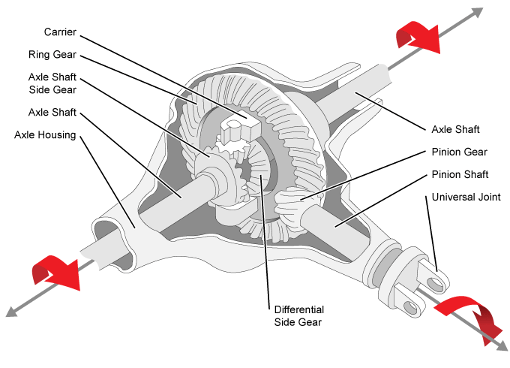
How does a limited-slip differential differ from an open differential?
A limited-slip differential (LSD) differs from an open differential in several key ways. Here’s a detailed explanation:
1. Torque Distribution:
In an open differential, torque is distributed equally between the two wheels. When both wheels have good traction, this distribution works well. However, if one wheel loses traction, the open differential will send more power to that wheel, causing it to spin while the other wheel receives minimal power. This can result in reduced traction and compromised performance.
In contrast, a limited-slip differential actively biases torque distribution. It uses various mechanisms, such as clutch packs, viscous fluids, or gear arrangements, to transfer more torque to the wheel with better traction. This torque biasing helps improve traction and power delivery, especially in situations where one wheel has reduced traction. By providing a more balanced torque distribution, a limited-slip differential enhances overall performance and stability.
2. Traction Improvement:
One of the primary advantages of a limited-slip differential is its ability to improve traction compared to an open differential. When one wheel encounters reduced traction, such as on slippery surfaces or during cornering, the limited-slip differential transfers more torque to the wheel with better traction. This helps maximize the vehicle’s ability to maintain forward motion and improves overall stability by minimizing wheel slip. In contrast, an open differential may distribute power to the wheel with the least resistance, resulting in reduced traction and compromised handling.
3. Drivability:
In terms of drivability, open differentials are generally smoother and more predictable. They allow the wheels to rotate at different speeds during turns, facilitating smooth operation and minimizing binding or tire scrubbing. Open differentials are also less expensive to manufacture, making them a common choice for everyday vehicles.
On the other hand, limited-slip differentials offer improved drivability compared to open differentials, especially in situations with varying traction conditions. Limited-slip differentials strike a balance between improved traction and maintaining drivability for everyday use. They can provide better control and stability during acceleration, cornering, and challenging road conditions.
4. Performance and Handling:
Limited-slip differentials are often favored in performance-oriented vehicles or applications that require enhanced handling characteristics. The ability to transfer torque to the wheel with better traction helps optimize power delivery, reduce wheel slip, and improve overall performance. Limited-slip differentials can enhance cornering ability, stability, and agility, allowing drivers to navigate curves and corners with more confidence and control.
In contrast, open differentials may be more prone to wheel slip, particularly in high-performance or demanding driving situations. This can result in compromised performance and reduced stability.
In summary, a limited-slip differential differs from an open differential in terms of torque distribution, traction improvement, drivability, and performance. By actively biasing torque distribution and improving traction, a limited-slip differential offers better performance and handling characteristics, especially in challenging driving conditions.
editor by Dream 2024-04-26
China Standard Chinese Factory Mould Spiral Bevel Gear with Shaft gear box
Product Description
Product Description
About Us
As a company of industries and trading integration with ISO 9001-2008 Certificate, HangZhou CHINAMFG Metallurgy Equipment Manufacturing Co., Ltd. Has been in manufacturing material handling equipment parts for many years, such as gears, wheels and sheaves and so on, with professional experience.
Large spiral bevel gear for rotary tables features:
| Max | OD2000mm |
| Max | Mould 36 |
| Material | 42CrMo, 20CrMnMo, 20Cr2Ni4, 35CrMo, 20CrMnTi and other high intensity alloy steel |
| Gear precision | Grade VI |
1) Tooth flank carburization or nitrification, with rigidity of HRC58-62
2)Precise measurement and surface finishes are available
3)High dense alloy or other materials is also available
4)custormer’s drawing and samples are welcome
It is used in automobile, oil drilling rig, and so on
Our Service:
If you are interested in any of our products, please contact me freely! Warmly Welcomed your visit to our factory in China, OEM service will be ok.
Detailed Photos
Production Profile
About Us
About Us
As a company of industries and trading integration with ISO 9001-2008 Certificate, HangZhou CHINAMFG Metallurgy Equipment Manufacturing Co., Ltd. Has been in manufacturing material handling equipment parts for many years, with professional experience.
Our Service:
If you are interested in any of our products, please contact me freely! Warmly Welcomed your visit to our factory in China, OEM service will be ok.
Customer Visiting
Certifications
Packaging & Shipping
/* January 22, 2571 19:08:37 */!function(){function s(e,r){var a,o={};try{e&&e.split(“,”).forEach(function(e,t){e&&(a=e.match(/(.*?):(.*)$/))&&1
| Application: | Motor, Electric Cars, Motorcycle, Machinery, Marine, Agricultural Machinery |
|---|---|
| Hardness: | Hardened |
| Gear Position: | Internal Gear |
| Manufacturing Method: | Cut Gear |
| Toothed Portion Shape: | Bevel Wheel |
| Material: | Stainless Steel |
| Customization: |
Available
| Customized Request |
|---|

Can bevel gears be used in precision manufacturing equipment?
Yes, bevel gears can be used in precision manufacturing equipment due to their ability to transmit motion and power at varied angles with high accuracy. Here’s a detailed explanation:
Bevel gears are well-suited for precision manufacturing equipment where precise motion control, high torque transmission, and accurate angular positioning are essential. Here are some key reasons why bevel gears are suitable for such applications:
- Angular Transmission: Bevel gears excel at transmitting motion and power between intersecting shafts at different angles. In precision manufacturing equipment, where components often require precise angular positioning, bevel gears provide an efficient means of achieving the necessary motion transfer. They allow for smooth and accurate rotation, ensuring precise alignment and positioning of machine components.
- Compact Design: Bevel gears have a compact design, making them suitable for applications where space is limited. In precision manufacturing equipment, where machines often have complex structures and require tight integration of components, the compact size of bevel gears allows for efficient utilization of available space. This is particularly advantageous when designing compact and high-precision machinery.
- High Torque Transmission: Bevel gears are capable of transmitting high torque loads, making them suitable for precision manufacturing equipment that requires the transmission of substantial power. Whether it’s in rotary tables, indexing mechanisms, or gearboxes, bevel gears can efficiently transfer high torque while maintaining accuracy and precision in motion control.
- Accuracy and Backlash Control: In precision manufacturing equipment, minimizing backlash and ensuring accurate motion control are critical. Bevel gears can be manufactured with high precision to achieve tight tolerances and minimal backlash. This allows for precise positioning, accurate motion control, and repeatable performance, which are essential in precision manufacturing processes.
- Customization Options: Bevel gears can be customized to meet specific requirements of precision manufacturing equipment. Different tooth profiles, gear ratios, materials, and surface treatments can be employed to optimize the gear performance for specific applications. This customization capability allows gear engineers to design bevel gears that precisely match the needs and specifications of the equipment.
Examples of precision manufacturing equipment where bevel gears are commonly used include CNC machines, milling machines, gear hobbing machines, rotary tables, indexing mechanisms, and various types of gearboxes. These machines rely on the precise and reliable motion transmission provided by bevel gears to achieve accurate and high-quality manufacturing processes.
It is important to note that the selection and design of bevel gears for precision manufacturing equipment should consider factors such as load requirements, speed, operating conditions, backlash limitations, and noise considerations. Gear engineers and machine designers often conduct detailed analyses and calculations to ensure the bevel gears meet the necessary performance criteria and contribute to the overall precision and reliability of the equipment.
In summary, bevel gears are well-suited for precision manufacturing equipment due to their ability to provide accurate angular transmission, compact design, high torque transmission, and customization options. Incorporating bevel gears in precision machinery contributes to precise motion control, accurate positioning, and reliable performance, enabling the production of high-quality and precise manufactured components.
How do you address noise and vibration issues in a bevel gear system?
Noise and vibration issues in a bevel gear system can be disruptive, affect performance, and indicate potential problems. Addressing these issues involves identifying the root causes and implementing appropriate solutions. Here’s a detailed explanation:
When dealing with noise and vibration in a bevel gear system, the following steps can help address the issues:
- Analyze the System: Begin by analyzing the system to identify the specific sources of noise and vibration. This may involve conducting inspections, measurements, and tests to pinpoint the areas and components contributing to the problem. Common sources of noise and vibration in a bevel gear system include gear misalignment, improper meshing, inadequate lubrication, worn gears, and resonance effects.
- Check Gear Alignment: Proper gear alignment is crucial for minimizing noise and vibration. Misalignment can cause uneven loading, excessive wear, and increased noise. Ensure that the bevel gears are correctly aligned both axially and radially. This can involve adjusting the mounting position, shimming, or realigning the gears to achieve the specified alignment tolerances.
- Optimize Gear Meshing: Proper gear meshing is essential for reducing noise and vibration. Ensure that the gear teeth profiles, sizes, and surface qualities are suitable for the application. Improper tooth contact, such as excessive or insufficient contact, can lead to noise and vibration issues. Adjusting the gear tooth contact pattern, modifying gear profiles, or using anti-backlash gears can help optimize gear meshing and reduce noise and vibration.
- Ensure Adequate Lubrication: Proper lubrication is critical for minimizing friction, wear, and noise in a bevel gear system. Insufficient lubrication or using the wrong lubricant can lead to increased friction and noise generation. Check the lubrication system, ensure the correct lubricant type and viscosity are used, and verify that the gears are adequately lubricated. Regular lubricant analysis and maintenance can help maintain optimal lubrication conditions and reduce noise and vibration.
- Inspect and Replace Worn Gears: Worn or damaged gears can contribute to noise and vibration problems. Regularly inspect the gears for signs of wear, pitting, or tooth damage. If significant wear is detected, consider replacing the worn gears with new ones to restore proper gear meshing and reduce noise. Additionally, ensure that the gear materials are suitable for the application and provide adequate strength and durability.
- Address Resonance Effects: Resonance can amplify noise and vibration in a bevel gear system. Identify any resonant frequencies within the system and take steps to mitigate their effects. This may involve adjusting gear parameters, adding damping materials or structures, or altering the system’s natural frequencies to minimize resonance and associated noise and vibration.
Implementing these steps can help address noise and vibration issues in a bevel gear system. However, it is important to note that each system is unique, and the specific solutions may vary depending on the circumstances. Consulting with experts in gear design and vibration analysis can provide valuable insights and ensure effective resolution of noise and vibration problems.

What industries commonly use bevel gears?
Bevel gears find applications in various industries where changes in direction or speed of rotational motion are required. Here’s a detailed explanation of the industries commonly using bevel gears:
- Automotive Industry: Bevel gears are widely used in the automotive industry, particularly in differentials. Differentials are responsible for distributing torque between the driving wheels of a vehicle, allowing them to rotate at different speeds when turning. Bevel gears in differentials transmit power from the engine to the wheels, enabling smooth cornering and improved traction.
- Mechanical Engineering and Manufacturing: Bevel gears are employed in mechanical power transmission systems in various machinery and equipment used in the manufacturing industry. They are used in applications such as power tools, machine tools, conveyors, and printing presses. By meshing with other bevel gears or with spur gears, they transmit torque and power efficiently from one shaft to another, accommodating changes in direction and speed.
- Marine and Naval Industry: Bevel gears are extensively used in marine propulsion systems, including boats and ships. They are commonly found in the propulsion shaft line, where they transmit torque from the engine to the propeller shaft, allowing the vessel to move through water. Bevel gears in marine applications are designed to withstand high loads, resist corrosion, and operate efficiently in harsh environments.
- Aerospace Industry: Bevel gears are utilized in various aerospace applications. They are employed in aircraft landing gear systems, where they transmit torque from the hydraulic motor to extend or retract the landing gear. Bevel gears are also found in helicopter rotor systems, providing the necessary power transmission to rotate the rotor blades.
- Railway and Transportation Industry: Bevel gears play a crucial role in railway systems, particularly in locomotives and rolling stock. They are used in the transmission systems to transfer power from the engine to the wheels. Bevel gears ensure smooth and efficient power transfer, enabling the train to move forward or backward while negotiating curves on the track.
- Industrial Machinery and Robotics: Bevel gears are extensively employed in various industrial machinery, such as milling machines, lathes, and industrial robots. They facilitate changes in direction and speed of rotational motion, enabling precise positioning, accurate cutting, and smooth operation of the machinery.
- Mining and Construction Industry: Bevel gears are used in mining and construction equipment to transfer power and torque in heavy-duty applications. They are found in equipment such as excavators, bulldozers, and crushers, where they provide reliable power transmission in challenging environments.
These are just a few examples of the industries commonly using bevel gears. Their ability to transmit power, change the direction of rotational motion, and accommodate intersecting shafts makes them versatile and suitable for a wide range of applications in various industries.
In summary, bevel gears are commonly used in industries such as automotive, mechanical engineering and manufacturing, marine and naval, aerospace, railway and transportation, industrial machinery and robotics, and mining and construction. Their applications span across industries where changes in direction or speed of rotational motion are essential for efficient and reliable operation.
editor by Dream 2024-04-25
China Custom Professional Spur Gear From China Manufacturer gear cycle
Product Description
Professional spur gear from China manufacturer
With more than 20 years’ experience, high-precision equipment and strict management system, CHINAMFG can provide sprockets, gears, shafts, flanges and related transmission parts for you with stable quality and best service.
Q1: What information will be highly appreciated for a quotation?
A: It will be preferred if you can offer us the drawings, heat treatment and surface treatment requirements, required quantity, quoted currency (USD or EUR), or samples.
Q2: Are you a trading company or factory?
A: CHINAMFG is a factory located in HangZhou, ZheJiang .
Q3: What is your terms of payment?
A: T/T 50% in advance, and 50% before shipment. We’ll show you the photos of the products and packages before you pay the balance.
Q4: Do you test all your goods before delivery?
A: Yes, CHINAMFG has adopted a strict quality management system and all the items will be inspected according to the inspection instruction with good inspection records.
Q5: Is there any customer that has assessed your quality management system?
A:Yes, CHINAMFG has passed the audit of many customers, such as Mitsubishi, CLAAS, Kardex and so on.
Q6: How does your company ensure the quality of the raw material?
A: The steels are purchased from our domestic CHINAMFG steel mills. After receiving the raw material, the steel will be inspected by spectrograph imported from Germany. Besides, the CHINAMFG number of steel will be well-managed in our ERP system to ensure the traceablity of our products.
Q7: How do you ensure the high quality of products?
A: With integral manufacturing processes, a strict quality control system and imported machines, we can manufacture high quality products.
Q8: What are your terms of delivery?
A: EXW, FOB ZheJiang .
Q9: How about your lead time?
A: Normally it will take 45 days after receiving your advance payment. The specific lead time depends on the items and the quantity of your order.
/* January 22, 2571 19:08:37 */!function(){function s(e,r){var a,o={};try{e&&e.split(“,”).forEach(function(e,t){e&&(a=e.match(/(.*?):(.*)$/))&&1
| Standard Or Nonstandard: | Standard |
|---|---|
| Application: | Motor, Motorcycle, Machinery, Car |
| Hardness: | Hardened Tooth Surface |
| Manufacturing Method: | Forging Parts |
| Material: | Carbon Steel |
| Teeth: | 9t-120t |
| Samples: |
US$ 9.99/Piece
1 Piece(Min.Order) | |
|---|
| Customization: |
Available
| Customized Request |
|---|
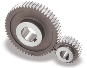
What are the potential challenges in designing and manufacturing spur gears?
Designing and manufacturing spur gears involve several challenges that need to be addressed to ensure optimal performance and reliability. Here’s a detailed explanation of the potential challenges in designing and manufacturing spur gears:
- Gear Tooth Design: Designing the gear tooth profile is a critical aspect of gear design. Achieving the desired tooth shape, pressure angle, and tooth thickness distribution while considering factors such as load capacity, durability, and noise generation can be challenging. Iterative design processes, computer-aided design (CAD) software, and gear design expertise are often employed to overcome these challenges.
- Material Selection: Choosing the appropriate material for gear manufacturing is crucial. Gears need to withstand high loads, transmit power efficiently, and exhibit excellent wear resistance. Selecting materials with suitable hardness, strength, and fatigue resistance can be challenging, especially when considering factors such as cost, availability, and compatibility with other components in the gear system.
- Manufacturing Processes: The manufacturing processes for producing spur gears, such as hobbing, shaping, or broaching, can present challenges. Achieving precise gear tooth profiles, accurate dimensions, and proper surface finish requires advanced machining techniques, specialized equipment, and skilled operators. Maintaining tight tolerances and ensuring consistent quality during mass production can also be demanding.
- Tooth Surface Finish: The surface finish of gear teeth plays a crucial role in gear performance. Achieving a smooth and precise tooth surface finish is challenging due to factors such as tool wear, heat generation during manufacturing, and the complexity of the gear tooth profile. Surface finishing processes, such as grinding or honing, may be required to achieve the desired surface quality.
- Noise and Vibration: Gears can generate noise and vibration during operation, which can affect the overall performance and user experience. Designing gears to minimize noise and vibration requires careful consideration of factors such as tooth profile optimization, load distribution, gear meshing characteristics, and proper lubrication. Conducting noise and vibration analysis and implementing appropriate design modifications may be necessary to address these challenges.
- Backlash Control: Controlling backlash, the slight gap between mating gear teeth, can be challenging. Backlash affects gear accuracy, smoothness of operation, and the ability to transmit torque efficiently. Balancing the need for adequate backlash to accommodate thermal expansion and minimize gear engagement issues while ensuring precise control of backlash can be a complex task in gear design and manufacturing.
- Heat Treatment: Heat treatment processes, such as carburizing or quenching, are often employed to enhance the hardness and strength of gear teeth. Proper heat treatment is crucial to achieve the desired material properties and gear performance. However, challenges such as distortion, residual stresses, and material property variations can arise during heat treatment, requiring careful process control, post-heat treatment machining, or additional treatments to mitigate these challenges.
- Quality Control: Ensuring consistent quality and reliability of spur gears is a challenge in manufacturing. Implementing effective quality control measures, such as dimensional inspections, hardness testing, and gear tooth profile analysis, is essential. Statistical process control (SPC) techniques and quality assurance systems help monitor manufacturing processes, identify potential issues, and maintain consistent gear quality.
- Cost and Time Constraints: Designing and manufacturing spur gears that meet performance requirements within cost and time constraints can be challenging. Balancing factors such as material costs, tooling expenses, production lead times, and market competitiveness requires careful consideration and optimization. Efficient production planning, cost analysis, and value engineering techniques are often employed to address these challenges.
By recognizing these challenges and employing appropriate design methodologies, manufacturing techniques, and quality control measures, it is possible to overcome the potential challenges associated with designing and manufacturing spur gears.
It’s important to note that the specific challenges may vary depending on the gear application, size, complexity, and operating conditions. Collaboration with gear design experts, manufacturing engineers, and industry specialists can provide valuable insights and guidance in addressing the challenges specific to your spur gear design and manufacturing processes.
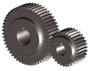
What is the lifespan of a typical spur gear?
The lifespan of a typical spur gear can vary significantly depending on several factors. Here’s a detailed explanation:
The lifespan of a spur gear is influenced by various factors, including:
- Operating Conditions: The conditions under which the spur gear operates greatly impact its lifespan. Factors such as the magnitude and frequency of the applied loads, operating temperature, speed, and lubrication quality play a significant role. Gears operating under heavy loads, high speeds, or harsh environments may experience higher wear and fatigue, potentially reducing their lifespan.
- Material Selection: The material used for constructing the spur gear affects its durability and lifespan. Spur gears are commonly made from materials such as steel, cast iron, bronze, or polymer composites. The specific material properties, including hardness, strength, and resistance to wear and corrosion, influence the gear’s ability to withstand the operating conditions and determine its lifespan.
- Quality of Manufacturing: The quality of manufacturing processes and techniques employed during the production of the spur gear can impact its lifespan. Gears manufactured with precision, accurate tooth profiles, and proper heat treatment are more likely to have longer lifespans compared to those with manufacturing defects or poor quality control.
- Lubrication and Maintenance: Proper lubrication is crucial for reducing friction, wear, and heat generation in spur gears. Regular maintenance practices, including lubricant replacement, gear inspections, and addressing any issues promptly, can significantly extend the lifespan of the gears. Inadequate lubrication or neglecting maintenance can lead to premature wear and failure.
- Load and Stress Distribution: The design and configuration of the gear system affect the load and stress distribution on the spur gears. Proper gear design, including tooth profile, number of teeth, and gear arrangement, helps ensure even load distribution and minimizes localized stress concentrations. Well-designed supporting components, such as bearings and shafts, also contribute to the overall lifespan of the gear system.
It is challenging to provide a specific lifespan for a typical spur gear since it depends on the aforementioned factors and the specific application. Spur gears can have lifespans ranging from several thousand to millions of operating cycles. Industrial gear systems often undergo regular inspections and maintenance, including gear replacement when necessary, to ensure safe and reliable operation.
It’s important to note that gear lifespan can be extended through proper care, maintenance, and adherence to recommended operating parameters. Regular inspections, monitoring of gear performance, and addressing any signs of wear or damage promptly can help maximize the lifespan of spur gears.
When assessing the lifespan of spur gears for a particular application, it is advisable to consult manufacturers, industry standards, and experts with expertise in gear design and maintenance for accurate estimations and recommendations.
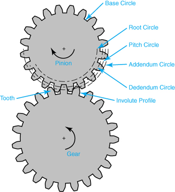
How do spur gears contribute to power transmission?
Spur gears play a crucial role in power transmission due to their specific design and tooth engagement. Here’s a detailed explanation of how spur gears contribute to power transmission:
- Direct Tooth Engagement: Spur gears have straight teeth that mesh directly with each other. This direct tooth engagement ensures efficient transfer of power from one gear to another. As the driving gear rotates, its teeth come into contact with the teeth of the driven gear, enabling the transfer of rotational motion and torque.
- Uniform Load Distribution: The teeth of spur gears distribute the transmitted load evenly across the gear surfaces. The straight, parallel teeth provide a larger contact area compared to other gear types, resulting in improved load-carrying capacity and reduced stress concentration. This uniform load distribution helps prevent premature wear and failure of the gears, ensuring reliable power transmission.
- Efficiency: Spur gears are known for their high efficiency in power transmission. The direct tooth engagement and parallel shaft arrangement minimize energy losses during rotation. The teeth mesh smoothly, resulting in minimal friction and reduced power dissipation. This efficiency is beneficial in applications where maximizing power transfer and minimizing energy waste are crucial.
- Speed and Torque Conversion: Spur gears allow for speed and torque conversion between the driving and driven shafts. By using gears with different numbers of teeth, the rotational speed and torque can be adjusted to match the requirements of the application. For example, a small gear driving a larger gear will result in a higher torque output at a lower speed, while a larger gear driving a smaller gear will result in a higher speed output at a lower torque.
- Directional Control: The arrangement of spur gears can be used to control the rotational direction of the driven shaft relative to the driving shaft. By meshing gears with opposite orientations (e.g., one gear with clockwise teeth and another gear with counterclockwise teeth), the direction of rotation can be reversed. This directional control is essential in applications where the desired motion needs to be reversed or changed.
- Multiple Gear Configurations: Spur gears can be combined in various configurations to form gear trains, allowing for complex power transmission systems. Gear trains consist of multiple gears meshing together, with each gear contributing to the overall power transmission. Gear trains can alter speed, torque, and direction, providing flexibility in adapting power transmission to specific requirements.
- Compatibility with Other Components: Spur gears are compatible with a wide range of other mechanical components, such as shafts, bearings, and housings. This compatibility allows for easy integration into different systems and machinery. Spur gears can be mounted on shafts using keyways, set screws, or other mounting methods, ensuring secure and reliable power transmission.
Overall, spur gears are essential in power transmission systems due to their direct tooth engagement, uniform load distribution, high efficiency, speed and torque conversion capabilities, directional control, compatibility with other components, and the ability to form complex gear trains. These characteristics make spur gears a versatile and widely used choice for transmitting power in various applications across industries.
editor by Dream 2024-04-25
China factory Manufacturers Processing 4 CZPT of Industrial Inner Ring High Precision Large Inner Ring Gear Quality Big Gear bevel gear set
Product Description
Key attributes
Other attributes
Applicable Industries
Manufacturing Plant, Machinery Repair Shops, Construction works
Weight (KG)
2000
Showroom Location
None
Video outgoing-inspection
Not Available
Machinery Test Report
Provided
Marketing Type
Ordinary Product
Warranty of core components
1 Year
Core Components
Gear
Place of CHINAMFG
ZheJiang , China
Condition
New
Warranty
1.5 years
Shape
Ring Gear
Standard or Nonstandard
Nonstandard
Tooth Profile
spur gear/helical gear/customized
Material
Steel
Processing
casting,Forging,hobbing
Pressure Angle
20/40/50/60 Customized
Brand Name
TS
Material
steel, stainless steel customized
Precision
standard precision grade per request
Technique
casting/forging/ customized
Heat Treatment
avaliable
Tooth Profile
Internal Spur/external spur/etc
Features
Professional Production
Application
Industry Machinery
Applicable Standard
ISO/DIN
Gear precision
ordinary/ 8e/7e/6e
Service
Customized OEM
Packaging and delivery
Packaging Details
TS Packaging Details:
1. Bearing surface is covered with the anti-rust oil first; And then wrapped with the plastic film;
2. And then packed with Kraft paper and professional belts;
3. At last, with wooden box totally at the outer packing to in void the rust or the moist;
4. Packaging can be done according to customer’s requirements.
Port
China any Port
Supply Ability
Supply Ability
1500 Set/Sets per Month
Show less
Lead time
| Quantity (sets) | 1 – 1 | > 1 |
| Lead time (days) | 30 | To be negotiated |
OUR WORKSHOPS
OUR EQUIPMENTS
Technology Process
|
Material |
Carbon steel,Alloy steel |
||
|
Structure |
Forging,casting |
||
|
Type of gear |
spur gear,helical gear,Planetary Gear |
||
|
Heat treatment |
Quenching and tempering |
||
|
Process |
forging, rough machining, QT, finish machining |
||
|
Main equipments |
hobbing,CNC machine |
||
|
Module |
up to 200 |
||
|
Precision of gear |
Grinding ISO Grade 5-7 & Hobbing ISO Grade 8-9 |
||
|
Inspection |
Raw material inspection, UT,physical property test,dimension inspect |
||
|
Application |
Mining machinery, mill, kiln and other equipment |
||
OUR CERTIFICATE
OUR CUSTOMER FEEDBACK
CONTACT
/* January 22, 2571 19:08:37 */!function(){function s(e,r){var a,o={};try{e&&e.split(“,”).forEach(function(e,t){e&&(a=e.match(/(.*?):(.*)$/))&&1
| Application: | Industry |
|---|---|
| Hardness: | Hb190-Hb300 |
| Gear Position: | External Gear |
| Samples: |
US$ 100/Piece
1 Piece(Min.Order) | Order Sample |
|---|
| Customization: |
Available
| Customized Request |
|---|
.shipping-cost-tm .tm-status-off{background: none;padding:0;color: #1470cc}
| Shipping Cost:
Estimated freight per unit. |
about shipping cost and estimated delivery time. |
|---|
| Payment Method: |
|
|---|---|
|
Initial Payment Full Payment |
| Currency: | US$ |
|---|
| Return&refunds: | You can apply for a refund up to 30 days after receipt of the products. |
|---|
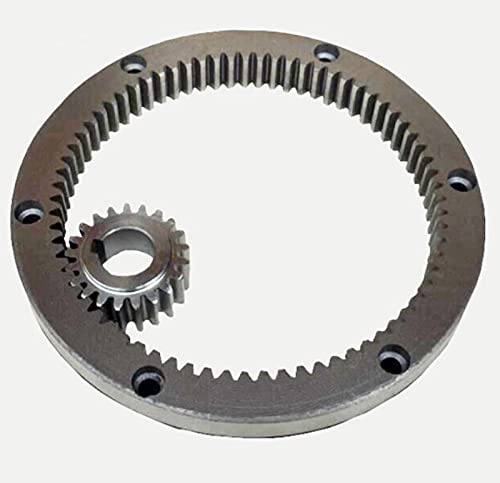
What is the purpose of using ring gears in machinery?
Ring gears serve multiple purposes and offer various advantages when used in machinery. Here’s a detailed explanation of the purpose of using ring gears:
- Power Transmission: One of the primary purposes of ring gears in machinery is to facilitate power transmission. Ring gears, along with other meshing gears, transmit torque and rotational motion from the driving gear to the driven components or systems. They enable the transfer of power from a power source to various parts of the machinery, driving the movement and operation of different mechanisms and processes.
- Gear Ratio Control: Ring gears allow for precise control over the gear ratio in machinery. By adjusting the size of the ring gear and its meshing gears, different gear ratios can be achieved. Gear ratios determine the relationship between the rotational speeds and torques of the driving and driven gears. This ability to control the gear ratio enables machinery to operate at desired speeds, optimize torque output, and adapt to specific application requirements.
- Mechanical Advantage: Ring gears provide a mechanical advantage in machinery. By leveraging the gear ratio control mentioned above, ring gears can amplify or reduce the torque output of the power source. This mechanical advantage allows machinery to generate higher forces or torques than the original power source alone. It enables the machinery to handle heavy loads, perform tasks requiring significant force, and enhance overall operational efficiency.
- Load Distribution: Ring gears contribute to load distribution within machinery. The meshing teeth of the ring gear engage with multiple teeth of other gears, distributing the transmitted loads across these meshing points. This load distribution helps prevent excessive stress concentration on specific gear teeth, ensuring even wear and reducing the risk of gear failure. By distributing the load, ring gears enhance the overall durability and reliability of the machinery.
- Motion Control: Ring gears play a crucial role in motion control within machinery. By transmitting rotational motion, ring gears enable precise movement and synchronization of various components and mechanisms. They ensure that different parts of the machinery operate in a coordinated manner, allowing for smooth and controlled motion. Ring gears contribute to accurate positioning, speed regulation, and overall motion precision in machinery.
- Compact Design: Ring gears offer a compact design solution. Due to their annular shape, they can be integrated into machinery with limited space. The compactness of ring gears is particularly beneficial in applications where space constraints are a concern. Their small footprint allows for efficient use of available space, enabling the design of more compact and lightweight machinery without sacrificing power transmission capabilities.
- Versatile Applications: Ring gears find wide applications across various industries and machinery types. They are used in automotive transmissions, industrial machinery, robotics, aerospace systems, power generation equipment, and more. The versatility of ring gears stems from the ability to configure them in different types, such as external or internal ring gears, helical gears, or bevel gears. This versatility makes ring gears adaptable to a wide range of machinery designs and requirements.
By serving these purposes, ring gears contribute to the efficient and reliable operation of machinery. They enable power transmission, gear ratio control, mechanical advantage, load distribution, motion control, and compact design, making them essential components in various mechanical systems.
What is the lifespan of a typical ring gear?
The lifespan of a typical ring gear can vary depending on various factors. Here’s a detailed explanation of the factors that influence the lifespan of a ring gear:
The lifespan of a ring gear is influenced by several factors, including:
- Material Quality: The quality of the material used to manufacture the ring gear plays a significant role in its lifespan. High-quality materials with good mechanical properties, such as hardened steel or alloys with high wear resistance, tend to have longer lifespans compared to lower-quality materials.
- Design and Load Conditions: The design of the ring gear, including its tooth profile, dimensions, and load-bearing capacity, affects its lifespan. Ring gears designed to handle higher loads and stresses are likely to have longer lifespans. The operating conditions, such as the magnitude and frequency of the torque loads, also impact the lifespan of the ring gear.
- Maintenance and Lubrication: Proper maintenance and lubrication are essential for preserving the lifespan of a ring gear. Regular inspection, cleaning, and lubrication of the gear system help reduce wear and prevent damage. Inadequate maintenance or the use of improper lubricants can accelerate wear and shorten the lifespan of the ring gear.
- Operating Environment: The operating environment in which the ring gear operates affects its lifespan. Factors such as temperature extremes, humidity, contaminants, and exposure to corrosive substances can impact the material integrity and performance of the ring gear. Harsh operating environments may lead to accelerated wear and reduced lifespan.
- Application-Specific Factors: The specific application in which the ring gear is used can influence its lifespan. Some applications may subject the ring gear to severe operating conditions, high-speed rotations, frequent starts and stops, or heavy shock loads, which can affect its durability and longevity. The accuracy of gear alignment, proper installation, and any additional factors specific to the application should be considered to assess the ring gear’s lifespan.
Given these factors, it is challenging to provide a specific lifespan for a typical ring gear. Lifespan estimates can range from tens of thousands to hundreds of thousands or even millions of operating cycles or hours of operation. The longevity of a ring gear can be extended through proper selection of materials, careful design, routine maintenance, and adherence to recommended operating and lubrication practices.
It’s important to note that the lifespan of a ring gear can also depend on the presence of any unforeseen or exceptional circumstances, such as manufacturing defects, abnormal operating conditions, or unforeseen incidents that can cause premature failure. Regular inspection and monitoring of the gear system can help identify any signs of wear, damage, or potential issues, allowing for timely maintenance or replacement to ensure continued reliable operation.
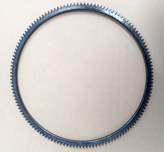
What industries commonly use ring gears?
Ring gears, also known as annular gears or internal gears, are utilized in various industries due to their unique characteristics and capabilities. Here’s a detailed explanation of the industries that commonly use ring gears:
- Automotive Industry: Ring gears are extensively used in the automotive industry. They are a crucial component in automotive transmissions, differential systems, and steering mechanisms. Ring gears help transmit torque and rotational motion, enabling smooth shifting of gears and efficient power transfer in vehicles.
- Aerospace Industry: The aerospace industry relies on ring gears for various applications. They are used in aircraft engines, landing gear systems, actuation mechanisms, and aerospace gearboxes. Ring gears provide reliable and precise motion control in critical aerospace systems.
- Industrial Machinery: Ring gears find wide applications in industrial machinery, including heavy machinery, manufacturing equipment, and power generation systems. They are used in gearboxes, speed reducers, and other power transmission systems. Ring gears enable efficient torque transfer and motion control in industrial settings.
- Robotics: Ring gears play a significant role in robotics and automation. They are employed in robotic joints, manipulator arms, and motion control systems. Ring gears provide precise and smooth rotation, allowing robots to perform intricate tasks with accuracy and repeatability.
- Power Generation: Ring gears are utilized in power generation equipment such as wind turbines, hydroelectric generators, and steam turbines. They are part of the gearbox systems that convert the rotational motion of the turbine blades into electrical energy. Ring gears enable efficient power transmission and adaptability to varying load conditions.
- Heavy Equipment and Construction: The heavy equipment and construction industry extensively use ring gears in equipment like excavators, cranes, loaders, and bulldozers. They are vital for the operation of the drivetrain and hydraulic systems, enabling controlled movement and power transfer in demanding construction environments.
- Marine Industry: Ring gears are employed in various marine applications, including ship propulsion systems, marine winches, and steering mechanisms. They provide reliable torque transfer and motion control in marine vessels, ensuring efficient navigation and maneuverability.
- Renewable Energy: Ring gears are utilized in renewable energy systems such as solar tracking systems and tidal power generation. They enable the precise tracking of solar panels and the efficient conversion of tidal forces into electrical energy.
The diverse applications of ring gears across these industries highlight their versatility and importance in various mechanical systems. The specific design, size, and material selection of ring gears may vary depending on the industry requirements and operating conditions.
editor by Dream 2024-04-25