Product Description
Gearbox Description
Standard Gearboxes Best price Parallel Shaft F series parallel bevel gear speed reducer
Features:
1. Modular design, compact structure. Extra-slim parallel shaft helical gearmotors are the perfect solution when space is limited
2. F series parallel shaft helical gearmotors are typically used in conveyors and materials processing applications
3. Multi-stage(2 or 3 stages) gear units for low output speed
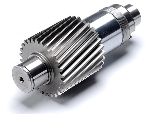
4. Hollow output shaft with keyed connection, shrink disk, splined hollow shaft, or torque arm
5. Can be combined with other types of gearboxes (Such as R Series, UDL Series)
6. Optional mounting options (foot-mounted, flange-mounted, shaft-mounted)
Gearbox Application
|
F Series Gearbox Reducer |
|
|
Product name |
F series of the gearbox hollow shaft model F107 oil seal transmission gearbox reducer reduction |
|
Warranty |
1 years |
|
Applicable Industries |
Manufacturing Plant |
|
Weight (KG) |
50KG |
|
Customized support |
OEM |
|
Gearing Arrangement |
Helical |
|
Output Torque |
1.8-2430N.M |
|
Input Speed |
1440, 2800,960,750 |
|
Output Speed |
0.5 to 200 |
|
Place of Origin |
China |
|
Product name |
F Series Parallel Shaft Gearbox Reducer |
|
Application |
Hardened Tooth Surface |
|
Installation |
Horizontal Type |
|
Layout |
Coaxial |
|
Gear Shape |
Helical |
|
Production Capacity |
800-1500PCS /Month |
|
Type |
Gear Reduction Motor |
|
Color |
Blue,Sliver or Customized |
|
Packing |
Wooden Box |
Detailed Photos
–Modular design, wide transmission ratio coverage, fine and reasonable distribution; Force reducer
–There are 11 types of frame specifications from F.27-F.157, and the transmission power range is 0.12KW-200KW;
–The shape design is suitable for omnidirectional universal installation configuration;
–The transmission is relatively accurate, covering the range of 3.77-281.71, and can be selected as required;
–The gear is grinded by high-precision gear grinding machine, with balanced transmission, low noise, and interstage efficiency of 98%;
–The transmission ratio of the F.R.reducer is extended to 31431, which is specially designed for special low-speed occasions
Editing and broadcasting of main materials
–Box: cast iron;
–Gear: low carbon alloy steel, carbonitriding treatment (after fine grinding, keep the tooth surface hardness of 60HRC, hard layer thickness>0.5mm);
–Flat key: 45 steel, with surface hardness above 45HRC.
Surface painting:
–Cast iron: sprayed with RAL7031 grey blue paint.
Parameter editing broadcast
Power: 0.18KW~200KW
Torque: 3N · m ~ 22500N · m
F series parallel shaft reducer
F series parallel shaft reducer
Output speed: 0.06~374r/minF series parallel shaft reducer [1]
/* January 22, 2571 19:08:37 */!function(){function s(e,r){var a,o={};try{e&&e.split(“,”).forEach(function(e,t){e&&(a=e.match(/(.*?):(.*)$/))&&1
| Application: | Packing Machine, Food Process, Lift, Crane, Agitat |
|---|---|
| Hardness: | Hardened Tooth Surface |
| Installation: | Horizontal Type |
| Layout: | Parallel |
| Gear Shape: | Bevel Gear |
| Step: | Single-Step |
| Samples: |
US$ 500/Piece
1 Piece(Min.Order) | |
|---|

How do you install a helical gear system?
Installing a helical gear system involves several steps to ensure proper alignment, engagement, and smooth operation. Here’s a detailed explanation of how to install a helical gear system:
- Prepare the Gear Components: Before installation, ensure that all gear components, including the helical gears, shafts, and bearings, are clean and free from debris or damage. Inspect the gears for any signs of wear, pitting, or tooth damage that may affect their performance.
- Check Gear Specifications: Verify that the helical gears you are installing are the correct size, tooth profile, and helix angle for the intended application. Refer to the gear specifications and engineering drawings to ensure compatibility and proper gear meshing.
- Align the Shafts: Proper shaft alignment is crucial for the smooth operation of a helical gear system. Align the shafts accurately using precision alignment tools such as dial indicators or laser alignment systems. Align the shafts both radially and axially to minimize misalignment and ensure the gears mesh correctly.
- Install Bearings: Mount the appropriate bearings onto the shafts to support the helical gears. Ensure that the bearings are properly lubricated and securely mounted according to the manufacturer’s instructions. Proper bearing installation is essential for minimizing friction, supporting the gears, and maintaining the alignment of the gear system.
- Install the Gears: Carefully position the helical gears onto their respective shafts. Ensure that the gears are properly aligned and engage smoothly without any binding or interference. Use appropriate tools such as gear pullers or hydraulic presses, if necessary, to facilitate gear installation. Follow any specific instructions provided by the gear manufacturer for gear mounting.
- Check Gear Meshing: After the gears are installed, check the gear meshing to ensure proper engagement. Rotate the gears by hand or using a suitable drive system and observe the tooth contact pattern. The gear meshing should be uniform, with proper tooth engagement along the full width of the gear teeth. Adjust the gear position or shim thickness, if needed, to achieve the desired tooth contact pattern.
- Secure the Gears: Once the gear meshing is satisfactory, secure the helical gears in place using appropriate fasteners such as shaft collars, set screws, or retaining rings. Ensure that the fasteners are tightened to the specified torque values but avoid over-tightening, which can lead to excessive bearing load or gear distortion.
- Provide Lubrication: Apply the recommended lubricant to the gear teeth and bearings according to the gear manufacturer’s instructions. Proper lubrication is crucial for reducing friction, dissipating heat, and extending the gear system’s service life. Regularly monitor the lubrication levels and replenish or replace the lubricant as needed.
- Perform Initial Testing: After installation, perform an initial test run of the helical gear system. Gradually increase the speed and load to ensure smooth operation and proper gear performance. Monitor for any unusual noise, vibration, or overheating, which may indicate misalignment, inadequate lubrication, or other issues that require adjustment or further inspection.
It’s important to note that the installation process may vary depending on the specific gear system, application, and manufacturer recommendations. Always refer to the gear manufacturer’s instructions and consult with experienced professionals or engineers when in doubt. Proper installation and maintenance are crucial for the optimal performance and longevity of a helical gear system.
What are the potential challenges in designing and manufacturing helical gears?
Designing and manufacturing helical gears can present various challenges that need to be addressed to ensure optimal performance and durability. Here’s a detailed explanation of the potential challenges encountered in designing and manufacturing helical gears:
- Complex Geometry: The geometry of helical gears is more complex compared to other gear types. The helical tooth profile requires precise calculations and manufacturing techniques to achieve the desired gear performance. Designers must account for factors such as helix angle, lead angle, tooth shape modification, and tooth contact pattern optimization. The complex geometry adds challenges to both the design and manufacturing processes.
- Manufacturing Accuracy: Achieving the required manufacturing accuracy for helical gears can be challenging. The gear teeth must have precise profiles and dimensions to ensure proper meshing and load distribution. The manufacturing processes, such as gear cutting (e.g., hobbing or grinding), must be carefully controlled to achieve the desired tooth geometry, surface finish, and dimensional accuracy. Maintaining tight tolerances and minimizing manufacturing variations are crucial to ensure the gears meet the design specifications.
- Axial Thrust and Bearing Considerations: Helical gears generate axial thrust forces due to the helix angle. The axial thrust can affect gear performance and may require additional measures to properly manage. Adequate bearing selection and support systems must be designed to accommodate the axial loads and ensure smooth gear operation. Consideration should also be given to the potential thrust-induced axial movement and its impact on gear alignment and system performance.
- Noise and Vibration: Helical gears can produce noise and vibration during operation, particularly if not designed or manufactured correctly. Factors such as improper tooth contact, misalignment, or excessive gear backlash can contribute to increased noise and vibration levels. Designers and manufacturers must carefully analyze and optimize the gear geometry, tooth contact patterns, and manufacturing processes to minimize noise and vibration and ensure quieter operation.
- Lubrication Challenges: Proper lubrication is critical for the smooth operation and longevity of helical gears. However, the helical tooth profile can pose challenges for lubricant distribution. The inclined teeth create a sliding action that may affect lubricant film formation and retention. Ensuring adequate lubrication to all gear surfaces, including the tooth flanks and root fillets, becomes important. Designing efficient lubrication systems and selecting appropriate lubricants that can withstand the sliding action and provide sufficient film thickness is crucial.
- Heat Dissipation: Helical gears can generate significant heat during operation, especially at high speeds or under heavy loads. Effective heat dissipation is essential to prevent overheating and premature wear. Designers and manufacturers need to consider heat dissipation mechanisms, such as proper housing design, cooling methods, and suitable materials with good thermal conductivity. Adequate ventilation and lubrication systems should also be designed to facilitate heat dissipation and maintain optimum operating temperatures.
- Tooling and Equipment: Manufacturing helical gears often requires specialized tooling and equipment. The gear cutting processes, such as hobbing or grinding, may necessitate specific tools, cutters, or grinding wheels. These tools must be properly selected, calibrated, and maintained to achieve accurate tooth profiles and finishes. The availability of suitable tooling and equipment, as well as the expertise to operate and maintain them, can be a challenge for gear manufacturers.
- Cost Considerations: Designing and manufacturing helical gears can involve higher costs compared to simpler gear types. The complexity of gear geometry, precision manufacturing requirements, specialized tooling, and additional considerations such as bearing support or noise reduction measures can contribute to increased production costs. Balancing the desired gear performance with cost considerations can be challenging for designers and manufacturers.
By addressing these potential challenges through careful design, precise manufacturing processes, and proper selection of materials and lubrication, engineers can overcome the complexities associated with designing and manufacturing helical gears and ensure high-quality gears that meet performance requirements and deliver long-term reliability.
How do helical gears contribute to quieter operation compared to other gears?
Helical gears offer quieter operation compared to other types of gears due to their specific design characteristics. Here’s a detailed explanation of how helical gears contribute to quieter operation:
- Inclined Tooth Profile: The primary reason for the quieter operation of helical gears is their inclined tooth profile. Unlike spur gears, which have straight teeth that engage abruptly, helical gears have angled teeth that gradually engage and disengage during rotation. This gradual engagement reduces the impact and shock loads that can generate noise and vibration.
- Smooth Tooth Contact: The inclined teeth of helical gears provide a larger contact area between the gear teeth as they mesh. This increased contact area allows for a smoother and more uniform transfer of force between the gears. The gradual contact and continuous meshing of teeth help in distributing the load over a larger surface, minimizing concentrated stress points that can cause noise and wear.
- Load Distribution: The inclined tooth profile of helical gears enables multiple teeth to be in contact at any given time. This distributed tooth engagement helps in spreading the load across a greater number of teeth, reducing the pressure on individual teeth and minimizing noise-causing stress concentrations. The load distribution also enhances the overall strength and durability of the gear mechanism.
- Reduced Backlash: Backlash refers to the play or clearance between the mating teeth of gears. Helical gears typically exhibit lower backlash compared to spur gears due to their inclined tooth configuration. The close contact and meshing of helical gear teeth minimize the gap between the mating gears, reducing backlash and the resulting noise and vibration that can occur when the gears change direction or load conditions.
- Smoothing and Noise Damping: The inclined teeth of helical gears have a rolling contact as they mesh, which helps in smoothing out any irregularities or imperfections on the tooth surfaces. This rolling action, combined with the continuous tooth contact, contributes to noise damping, reducing the transmission of vibrations and noise through the gear mechanism.
- Lubrication and Surface Treatment: Proper lubrication and surface treatment of helical gears can further enhance their quiet operation. Lubricants help in reducing friction and wear between the gear teeth, minimizing noise generation. Additionally, surface treatments such as honing or grinding can improve the tooth surface quality, reducing friction, noise, and vibration during gear operation.
Collectively, the inclined tooth profile, smooth tooth contact, load distribution, reduced backlash, smoothing and noise damping effects, and proper lubrication contribute to the quieter operation of helical gears. These design characteristics make helical gears particularly suitable for applications where noise reduction, smooth operation, and low vibration levels are desired, such as in automotive transmissions, industrial machinery, and precision equipment.


editor by Dream 2024-04-24