Product Description
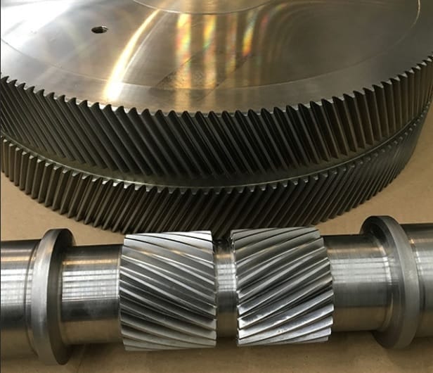
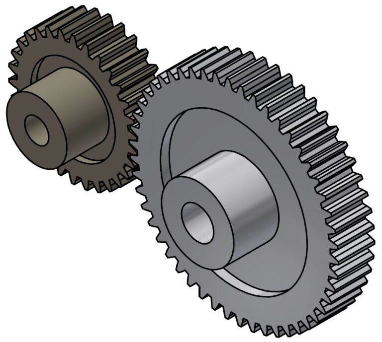
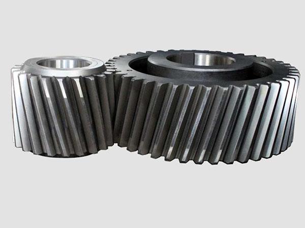
Food grade Pe 1000 Helical Gear
UHMW-PE(Ultra high Molecular Weight Polyethylene )is a thermoplastic engineering plastic with the average molecular weight more than 9.0 million. (PE only has the molecular weight between 20 to 2 hundred thousand. ) This kind of material with 5 top performance of high-wear-resistance, good-chemical resistance, low-temperature resistance, self-lubrication and high-impact resistance, which is regarded as a “surprised” engineering plastic of excellent comprehensive capacity and competitive price.
Main characteristics:
1. Very high-wear resistance, 7 times wear resistance than steel, 4 times than PTFE
2. Very high anti-impact resistance, 2 times impact resistance than PC, 5 times than ABS.
3. Good self-lubrication, the same as PTFE, better than steel and brass appended lubricating oil.
4. Good anti-corrosion resistance, it has very stable chemicals property and can endure the corrosion of
All kinds of corrosive medium and organic solvent in certain rang of temperature and humidity.
5. Very high-inadhesion resistance, the surface of product hardly affixes other material.
6. Very high-impact resistance, 10 times impact resistance than PA66, 8 times than PTFE.
7. Good low temperature resistance, in liquefied nitrogen (- 196º C), it still has the prolongation.
Few other materials can reach to this performance.
8. Non-toxic and clean property, UHMW-PE, which is the material that Food and Drug Administration (FDA) and United States Department of Agriculture (ASDA) permit to apply in food and medicine fields.
| Property | Item No. | Unit | Value | |
| Mechanical Properties | 1 | Density | g/cm3 | 0.94-0.96 |
| 2 | average molecular weight | g/mol | More than 9.0 million | |
| 3 | Tensile strength (23ºCin air) | MPa | 22 | |
| 4 | Breaking strength | MPa | 42 | |
| 5 | Tensile strain at break | % | 600 | |
| 6 | Charpy impact strength (notched) | mJ/mm 2 | No break | |
| 7 | Ball indentation hardness | N/mm 2 | 42 | |
| 8 | Shore D hardness | — | D65 | |
| 9 | Abrading(sand slurry experiment) | — | 100 | |
/* January 22, 2571 19:08:37 */!function(){function s(e,r){var a,o={};try{e&&e.split(“,”).forEach(function(e,t){e&&(a=e.match(/(.*?):(.*)$/))&&1
| Size: | According to Drawing or Sample |
|---|---|
| Color: | White, Black, Green, Yellow, Blue, Red |
| Transport Package: | Packing in Wood Pallet |
| Specification: | RoHS, FDA |
| Trademark: | Guangzhou Engineering Plastics |
| Origin: | Guangzhou, Gd, Cn |
| Customization: |
Available
| Customized Request |
|---|

What is the purpose of using helical gears in power transmission?
Helical gears are commonly used in power transmission systems for various purposes. Here’s a detailed explanation of the purpose and advantages of using helical gears in power transmission:
- Smooth and Efficient Power Transfer: One of the primary purposes of using helical gears in power transmission is to achieve smooth and efficient transfer of power. The inclined tooth profile of helical gears allows for gradual and continuous engagement of teeth, minimizing shock loads and ensuring a more uniform distribution of force. This results in smoother power transmission with reduced noise, vibration, and wear.
- High Torque Transmission: Helical gears are known for their high torque-carrying capacity. The inclined teeth of helical gears enable a larger tooth contact area compared to other gear types such as spur gears. This increased tooth contact area allows helical gears to transmit higher torque, making them suitable for applications that require the transfer of large amounts of power, such as in industrial machinery, automotive drivetrains, and heavy-duty equipment.
- Variable Speed Ratios: Helical gears can be designed with different numbers of teeth and varying helix angles, allowing for a wide range of speed ratios. By selecting the appropriate combination of gears, the rotational speed and torque can be adjusted to meet the requirements of the power transmission system. This flexibility in speed ratios makes helical gears versatile in applications where variable speed control is necessary.
- Reduction of Noise and Vibration: The inclined tooth profile and gradual engagement of helical gears contribute to the reduction of noise and vibration in power transmission systems. Compared to spur gears, helical gears generate less noise and vibration due to their smoother meshing characteristics and improved load distribution. This makes helical gears particularly beneficial in applications where noise reduction and smooth operation are important considerations, such as in automotive transmissions and precision equipment.
- Compact Design: Helical gears can achieve high gear ratios within a relatively compact design. The inclined teeth of helical gears allow for more teeth to be in contact at any given time, enabling a higher gear ratio compared to spur gears of the same size. This compactness is advantageous when there are space constraints or when a smaller gear mechanism is desired without sacrificing performance or torque capacity.
- High Reliability and Durability: Helical gears are designed to distribute the load over multiple teeth, resulting in improved load-carrying capacity and enhanced gear strength. The inclined tooth profile allows for a larger contact area, reducing stress concentrations and increasing the gear’s resistance to wear and fatigue. These factors contribute to the high reliability and durability of helical gears, making them suitable for demanding power transmission applications that require long service life.
In summary, the purpose of using helical gears in power transmission is to achieve smooth and efficient power transfer, high torque transmission, variable speed control, noise and vibration reduction, compact design, and high reliability. These advantages make helical gears widely used in various industries, including automotive, manufacturing, energy, and many other applications that require reliable and efficient power transmission.

How do you retrofit an existing mechanical system with helical gears?
Retrofitting an existing mechanical system with helical gears involves replacing the current gear system with helical gears to improve performance, efficiency, or address specific requirements. The process requires careful planning, analysis, and implementation to ensure a successful retrofit. Here is a detailed explanation of how to retrofit an existing mechanical system with helical gears:
- Assess the Existing System: Begin by thoroughly assessing the existing mechanical system. Understand its design, operating conditions, gear specifications, and performance limitations. Identify the reasons for retrofitting, such as the need for increased load capacity, improved efficiency, noise reduction, or other specific requirements.
- Define Retrofit Objectives: Clearly define the objectives of the retrofit. Determine the specific improvements or modifications desired from the retrofit. This could include increasing torque capacity, reducing backlash, improving gear meshing characteristics, or optimizing gear ratios. Having well-defined objectives will guide the retrofitting process.
- Perform Gear Design and Analysis: Based on the defined objectives, conduct gear design and analysis to determine the appropriate helical gear configuration. Consider factors such as gear size, tooth profile, helix angle, module or diametral pitch, and gear material. Use engineering calculations, software simulations, or consult with gear design experts to ensure the selected helical gears meet the retrofit objectives and are compatible with the existing system.
- Modify Gear Housing and Mounting: In some cases, retrofitting with helical gears may require modifications to the gear housing or mounting arrangements. Ensure that the gear housing can accommodate the helical gears and provide proper alignment and support. Modify or adapt the housing as necessary to ensure a precise fit and alignment of the new gear system.
- Manufacture or Source Helical Gears: Once the gear design is finalized, manufacture or source the helical gears according to the specifications determined during the design phase. Work with experienced gear manufacturers or suppliers who can provide high-quality helical gears that meet the required specifications and performance criteria.
- Installation and Alignment: Remove the existing gears and install the helical gears in the mechanical system. Ensure proper alignment of the gears to maintain smooth operation and minimize wear. Follow recommended installation procedures and torque specifications provided by the gear manufacturer. Consider using alignment tools, such as dial indicators or laser alignment systems, to achieve precise gear alignment.
- Test and Fine-tune: After installation, conduct thorough testing of the retrofit system. Monitor performance, check for any abnormal vibrations, noise, or operating issues. Fine-tune the system as needed, making adjustments to gear meshing, lubrication, or other parameters to optimize performance and ensure the retrofit objectives are met.
- Monitor and Maintain: Once the retrofit is complete, establish a regular monitoring and maintenance schedule. Periodically inspect the helical gears for wear, perform lubrication checks, and address any maintenance requirements. Regular monitoring and maintenance will help ensure the longevity and optimal performance of the retrofit system.
Retrofitting an existing mechanical system with helical gears can significantly enhance its performance, efficiency, and reliability. However, it is essential to carefully plan and execute the retrofitting process to achieve the desired outcomes. Consulting with gear design experts and experienced professionals can provide valuable guidance and expertise throughout the retrofitting process.

How do you choose the right size helical gear for your application?
Choosing the right size helical gear for your application involves considering several factors to ensure optimal performance and reliability. Here’s a detailed explanation of the steps involved in selecting the right size helical gear:
- Determine the Application Requirements: Start by understanding the specific requirements of your application. Consider factors such as the desired speed ratio, torque requirements, power transmission capacity, operating conditions (including temperature, lubrication, and environment), and any special considerations unique to your application.
- Calculate the Gear Parameters: Based on the application requirements, calculate the necessary gear parameters. These parameters include the pitch diameter, number of teeth, module or pitch, pressure angle, helix angle, face width, and center distance. These calculations can be performed using gear design formulas or software tools specifically designed for gear selection.
- Consider Load and Strength: Evaluate the load conditions that the helical gear will experience. Take into account factors such as the transmitted torque, radial loads, axial loads, and dynamic forces. Ensure that the selected gear can withstand the anticipated loads and provide sufficient strength and durability. Consider factors such as gear material, heat treatment, and tooth geometry to ensure adequate load-carrying capacity and resistance to wear and fatigue.
- Check Gear Meshing and Alignment: Proper gear meshing and alignment are crucial for smooth operation and efficient power transmission. Ensure that the selected gear size and tooth profile allow for proper meshing with the mating gear. Consider factors such as backlash, tooth contact pattern, and alignment tolerances to minimize noise, vibration, and wear. Proper alignment of shafts and bearings is also important for optimal gear performance.
- Consider Space Limitations: Evaluate the available space in your application for gear installation. Consider factors such as the gear diameter, length, and clearance requirements. Ensure that the selected gear size can fit within the available space without interfering with other components or causing installation challenges.
- Consult Manufacturer’s Guidelines: Refer to the manufacturer’s guidelines, catalogs, and technical documentation for the specific type and brand of helical gear you are considering. Manufacturers often provide recommendations, selection charts, and engineering support to assist in choosing the right size gear for different applications. It’s beneficial to leverage their expertise and knowledge.
- Consider Cost and Availability: Evaluate the cost and availability of the selected helical gear. Consider factors such as the gear’s price, lead time, availability of spare parts, and any additional costs associated with installation or maintenance. Balance your requirements with the available budget and ensure that the chosen gear offers a cost-effective solution without compromising performance or quality.
By following these steps and considering the application requirements, load conditions, gear parameters, meshing characteristics, space limitations, manufacturer’s guidelines, and cost factors, you can choose the right size helical gear that meets your specific application needs.
It’s important to note that gear selection can be a complex process, and it may be beneficial to consult with an experienced engineer or gear specialist to ensure an accurate and optimized gear sizing for your specific application.


editor by CX 2024-04-04