Product Description
Custom casting girth gear 42CrMo Rotary Kiln large ring gear high quality large diameter ring gear
Product Description
Process:
Forging/Casting
Normalizing&Tempering-Proof Machinnig
Quenching&Tempering
Finish Machining(Teeth Grinding)
We can offer you in various process conditions Solutions for Many End Markets and Applications
–Mining
–Metallurgy
–Power Generation
–Cement Plant
–Port Machinery
–Oil and natural
–Paper making
–OEM gear case
–General Industrial
| Specification | Machining Scope |
| Size | OD Max 16m |
| One Piece of Gear: OD Max 13m | |
| Assemble Gear: According to drawings | |
| Hobbing Modulus | 10-60 |
| Milling Modulus | Up to 120 |
| Spiral Modulus | 1-15 |
| Accuracy Grade | Milling: 6 grade |
| Hobbing: 8 grade | |
| Material | Alloy steel: 42CrMo4, 34CrNiMo6 etc. |
| Carbon steel: C45E, 1030 | |
| Carburizing steel | |
| Quenched and tempered steel | |
| Heat treatment | Quenching & Tempering, Surface Quenching |
| Teeth Profile | Spur, Helical, Herringbone, Crown, Spiral, Worm and shaft |
Inspection and Test Outline of Girth Gear:
| No. | Item | Inspection Area | Acceptance Criteria | Inspection Stage | Certificates |
| 1 | Chemical Composition | Sample | Material Requirement | When Smelting After Heat Treatment |
Chemical Composition Report |
| 2 | Mechanical Properties | Sample(Test Bar on the Gear Body) | Technical Requirement | After Heat Treatment | Mechanical Properties Report |
| 3 | Heat Treatment | Whole Body | Manufacturing Standard | During Heat Treatment | Heat Treatment Report Curves of Heat Treatment |
| 4 | Hardness Test | Tooth Surface, 3 Points Per 90° | Technical Requirement | After Heat Treatment | Hardness Teat Report |
| After Semi Finish Machining | |||||
| 5 | Dimension Inspection | Whole Body | Drawing | After Semi Finish Machining | Dimension Inspection Report |
| Finish Machining | |||||
| 6 | Magnetic Power Test (MT) | Tooth Surface | Agreed Standard | After Finish Gear Hobbing | MT Report |
| 7 | UT | Spokes Parts | Agreed Standard | After Rough Machining | UT Report |
| After Welded | |||||
| After Semi Finish Machining | |||||
| 8 | PT | Defect Area | No Defect Indicated | After Digging After Welded |
PT Record |
| 9 | Mark Inspection | Whole Body | Manufacturing Standard | Final Inspection | Pictures |
| 10 | Appearance Inspection | Whole Body | CIC’s Requirement | Before Packing (Final Inspection) |
|
| 11 | Anti-rust Inspection | Whole Body | Agreed Anti-rust Agent | Before Packing | Pictures |
| 12 | Packing Inspection | Whole Body | Agreed Packing Form | During Packing | Pictures |
Testing Process:
· QA DOC: Chemical Composition Report, Mechanical Properties Report, UT Report, Heat Treatment Report, Dimensions Check Report
· UT test: 100% ultrasonic test according to EN15718-3, SA388, Sep 1921 C/c etc.
· Heat Treatment Report: provide original copy of heat treatment curve/time table.
FAQ
1. What is your minimum order quantity?
Our minimum order quantity typically ranges from 5 to 100 pieces, depending on the product and material.
2. Can you provide custom designs?
Yes, we specialize in providing custom designs based on your specific requirements.
3. What is your production capacity?
Our production capacity varies depending on the product and material, but we have the capability to produce millions of pieces per year.
4. What is your lead time for orders?
Our lead time for orders is typically 4-6 weeks for production and delivery.
5. Do you offer quality control and testing?
Yes, we have strict quality control measures in place and offer testing services, including non-destructive testing, to ensure the quality of our products.
/* March 10, 2571 17:59:20 */!function(){function s(e,r){var a,o={};try{e&&e.split(“,”).forEach(function(e,t){e&&(a=e.match(/(.*?):(.*)$/))&&1
| Application: | Machinery, Industry |
|---|---|
| Hardness: | According to Customers′ Requirements |
| Gear Position: | Internal Gear |
.shipping-cost-tm .tm-status-off{background: none;padding:0;color: #1470cc}
|
Shipping Cost:
Estimated freight per unit. |
about shipping cost and estimated delivery time. |
|---|
| Payment Method: |
|
|---|---|
|
Initial Payment Full Payment |
| Currency: | US$ |
|---|
| Return&refunds: | You can apply for a refund up to 30 days after receipt of the products. |
|---|
Can spur gears be used in automotive applications?
Yes, spur gears can be used in automotive applications. Here’s a detailed explanation:
Spur gears are one of the simplest and most commonly used types of gears. They consist of cylindrical teeth that are parallel to the gear axis and mesh with each other to transmit power and motion. While other gear types like helical gears or bevel gears are often preferred in certain automotive applications, spur gears still find their place in various automotive systems and components.
1. Transmissions:
Spur gears are commonly found in manual transmissions, especially in lower gears. They are used to achieve a direct and efficient power transfer between the engine and the wheels. Spur gears in transmissions are designed to handle high torque loads and provide reliable performance.
2. Differential:
In automotive differentials, which distribute power between the wheels while allowing them to rotate at different speeds, spur gears are often employed. They are used in the differential gear train to transfer torque from the driveshaft to the wheels. The simplicity and robustness of spur gears make them suitable for this application.
3. Starter Motors:
Spur gears are commonly used in starter motors to crank the engine when starting a vehicle. They provide high torque and efficient power transmission to rotate the engine’s crankshaft and initiate the combustion process. Starter motor spur gears are designed to handle the initial load and engage smoothly with the engine’s flywheel.
4. Timing Systems:
In automotive timing systems, where precise synchronization of engine components is crucial, spur gears can be used. They are employed in timing belts or chains to drive the camshafts, ensuring proper valve timing and engine performance. Spur gears in timing systems contribute to accurate and reliable engine operation.
5. Accessories and Auxiliary Components:
Spur gears are also utilized in various automotive accessories and auxiliary components. They can be found in power window mechanisms, windshield wipers, power steering systems, and other mechanisms that require controlled and synchronized motion. Spur gears provide cost-effective and efficient power transmission for these applications.
It’s important to note that while spur gears have their advantages, they also have certain limitations. They can generate more noise and vibration compared to gears with helical or bevel tooth profiles. Additionally, spur gears are not as suitable for high-speed or high-torque applications as other gear types.
Overall, spur gears have a significant presence in automotive applications, particularly in manual transmissions, differentials, starter motors, timing systems, and various auxiliary components. Their simplicity, reliability, and cost-effectiveness make them a viable choice for specific automotive gear applications.
What is the lifespan of a typical spur gear?
The lifespan of a typical spur gear can vary significantly depending on several factors. Here’s a detailed explanation:
The lifespan of a spur gear is influenced by various factors, including:
- Operating Conditions: The conditions under which the spur gear operates greatly impact its lifespan. Factors such as the magnitude and frequency of the applied loads, operating temperature, speed, and lubrication quality play a significant role. Gears operating under heavy loads, high speeds, or harsh environments may experience higher wear and fatigue, potentially reducing their lifespan.
- Material Selection: The material used for constructing the spur gear affects its durability and lifespan. Spur gears are commonly made from materials such as steel, cast iron, bronze, or polymer composites. The specific material properties, including hardness, strength, and resistance to wear and corrosion, influence the gear’s ability to withstand the operating conditions and determine its lifespan.
- Quality of Manufacturing: The quality of manufacturing processes and techniques employed during the production of the spur gear can impact its lifespan. Gears manufactured with precision, accurate tooth profiles, and proper heat treatment are more likely to have longer lifespans compared to those with manufacturing defects or poor quality control.
- Lubrication and Maintenance: Proper lubrication is crucial for reducing friction, wear, and heat generation in spur gears. Regular maintenance practices, including lubricant replacement, gear inspections, and addressing any issues promptly, can significantly extend the lifespan of the gears. Inadequate lubrication or neglecting maintenance can lead to premature wear and failure.
- Load and Stress Distribution: The design and configuration of the gear system affect the load and stress distribution on the spur gears. Proper gear design, including tooth profile, number of teeth, and gear arrangement, helps ensure even load distribution and minimizes localized stress concentrations. Well-designed supporting components, such as bearings and shafts, also contribute to the overall lifespan of the gear system.
It is challenging to provide a specific lifespan for a typical spur gear since it depends on the aforementioned factors and the specific application. Spur gears can have lifespans ranging from several thousand to millions of operating cycles. Industrial gear systems often undergo regular inspections and maintenance, including gear replacement when necessary, to ensure safe and reliable operation.
It’s important to note that gear lifespan can be extended through proper care, maintenance, and adherence to recommended operating parameters. Regular inspections, monitoring of gear performance, and addressing any signs of wear or damage promptly can help maximize the lifespan of spur gears.
When assessing the lifespan of spur gears for a particular application, it is advisable to consult manufacturers, industry standards, and experts with expertise in gear design and maintenance for accurate estimations and recommendations.
What is a spur gear and how does it work?
A spur gear is a type of cylindrical gear with straight teeth that are parallel to the gear axis. It is one of the most common and simplest types of gears used in various mechanical systems. Spur gears work by meshing together to transmit rotational motion and torque between two parallel shafts. Here’s a detailed explanation of spur gears and how they work:
A spur gear consists of two or more gears with cylindrical shapes and an equal number of teeth. These gears are mounted on parallel shafts, and their teeth mesh together to transfer rotational motion from one gear to another. The gear with power input is called the “drive gear” or “driver,” while the gear receiving the power output is called the “driven gear” or “follower.”
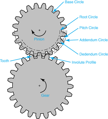
The key characteristics and components of spur gears include:
- Teeth: Spur gears have straight teeth that are cut parallel to the shaft axis. The teeth are evenly spaced around the circumference of the gear. The number of teeth determines the gear ratio and affects the speed and torque transmission between the gears.
- Pitch Diameter: The pitch diameter is the theoretical diameter of the gear at the point where the teeth mesh. It is determined by the number of teeth and the module or diametral pitch of the gear.
- Module or Diametral Pitch: The module is a parameter used in metric gear systems, while the diametral pitch is used in imperial gear systems. They define the tooth size and spacing of the gear. The module is the ratio of the pitch diameter to the number of teeth, while the diametral pitch is the number of teeth per inch of pitch diameter.
- Pressure Angle: The pressure angle is the angle between the line tangent to the tooth profile at the pitch point and a line perpendicular to the gear axis. Common pressure angles for spur gears are 20 degrees and 14.5 degrees.
- Meshing: Spur gears mesh by engaging their teeth, creating a point or line contact between the contacting surfaces. The teeth transfer rotational motion and torque from the drive gear to the driven gear.
- Gear Ratio: The gear ratio is determined by the number of teeth on the drive gear and the driven gear. It defines the relationship between the input speed and the output speed. The gear ratio can be calculated by dividing the number of teeth on the driven gear by the number of teeth on the drive gear.
- Operation: As the drive gear rotates, its teeth come into contact with the teeth of the driven gear. The contact between the teeth transfers rotational motion and torque from the drive gear to the driven gear. The meshing teeth maintain a constant speed ratio, allowing for the transmission of power between the shafts. The direction of rotation can be changed by meshing gears with an odd or even number of teeth.
Spur gears offer several advantages, including simplicity, ease of manufacture, efficiency, and reliability. They are commonly used in a wide range of applications, including machinery, automotive systems, appliances, power tools, and more.
In conclusion, spur gears are cylindrical gears with straight teeth that mesh together to transfer rotational motion and torque between parallel shafts. Their simple and efficient design makes them a popular choice for various mechanical systems.


editor by CX 2024-01-04