Product Description
Key attributes
Other attributes
Applicable Industries
Manufacturing Plant, Machinery Repair Shops, Energy & Mining
Weight (KG)
1650
Showroom Location
None
Video outgoing-inspection
Provided
Machinery Test Report
Provided
Marketing Type
Hot Product 2571
Warranty of core components
1 Year
Core Components
Gear
Place of CHINAMFG
ZheJiang , China
Condition
New
Warranty
1.5 years
Shape
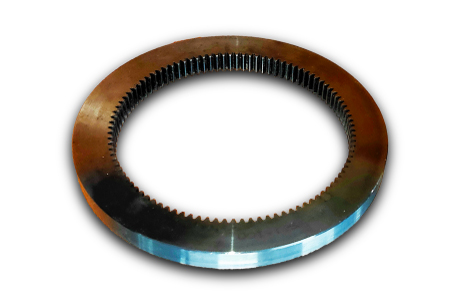
Ring Gear
Standard or Nonstandard
Nonstandard
Tooth Profile
Spur
Material
Steel
Processing
Casting
Pressure Angle
20°
Brand Name
HangZhou
Product Name
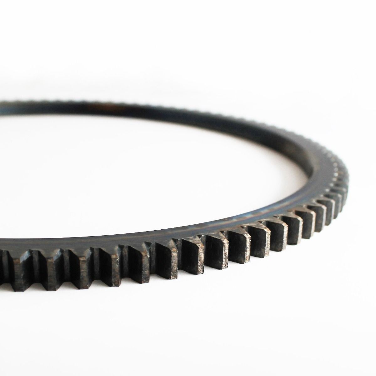
custom large diameter alloy steel spur casting large ring gear
Application
Cement kiln
Gear Machining
Gear milling
Module of Gear:
8-120
OD For Gear Wheel:
MAX.13 000 mm
Height For CHINAMFG
MAX. 1200 mm
Certificate
ISO 9001:2015
Tolerance
+/-0.01mm
Heat treatment
QT
Surface Treatment
Surface Hardening or Carburizing and Quenching
Packaging and delivery
Packaging Details
Package for Cement kiln custom large diameter ring gear transmission alloy steel spur casting large ring gear is wooden box and adapts to CHINAMFG transport
Port
ZheJiang ,HangZhou or Others
Supply Ability
Supply Ability
9000 Ton/Tons per Year
OUR WORKSHOPS
OUR EQUIPMENTS
Technology Process
|
Material |
Carbon steel,Alloy steel |
||
|
Structure |
Forging,casting |
||
|
Type of gear |
spur gear,helical gear,Planetary Gear |
||
|
Heat treatment |
Quenching and tempering |
||
|
Process |
forging, rough machining, QT, finish machining |
||
|
Main equipments |
hobbing,CNC machine |
||
|
Module |
up to 200 |
||
|
Precision of gear |
Grinding ISO Grade 5-7 & Hobbing ISO Grade 8-9 |
||
|
Inspection |
Raw material inspection, UT,physical property test,dimension inspect |
||
|
Application |
Mining machinery, mill, kiln and other equipment |
||
OUR CERTIFICATE
OUR CUSTOMER FEEDBACK
CONTACT
/* January 22, 2571 19:08:37 */!function(){function s(e,r){var a,o={};try{e&&e.split(“,”).forEach(function(e,t){e&&(a=e.match(/(.*?):(.*)$/))&&1
| Application: | Industry |
|---|---|
| Hardness: | Hb190-Hb300 |
| Gear Position: | External Gear |
| Samples: |
US$ 100/Piece
1 Piece(Min.Order) | Order Sample |
|---|
| Customization: |
Available
| Customized Request |
|---|
.shipping-cost-tm .tm-status-off{background: none;padding:0;color: #1470cc}
| Shipping Cost:
Estimated freight per unit. |
about shipping cost and estimated delivery time. |
|---|
| Payment Method: |
|
|---|---|
|
Initial Payment Full Payment |
| Currency: | US$ |
|---|
| Return&refunds: | You can apply for a refund up to 30 days after receipt of the products. |
|---|
How do you install a ring gear system?
Installing a ring gear system requires careful attention to ensure proper alignment, engagement, and secure attachment. Here’s a detailed explanation of the installation process:
- Prepare the Components: Gather all the necessary components for the ring gear system installation, including the ring gear, driving gear, and any other associated gears or components.
- Clean the Surfaces: Thoroughly clean the mounting surfaces of the gears and the mating components to remove any dirt, debris, or old lubricant. Clean surfaces will ensure better engagement and prevent contamination of the gear system.
- Inspect the Gears: Carefully inspect the ring gear and other gears for any signs of damage, wear, or misalignment. Check the teeth for any chips, cracks, or irregularities that may affect the performance of the gear system. Replace any damaged or worn gears before proceeding with the installation.
- Ensure Proper Alignment: Align the ring gear and the driving gear in the desired configuration. The alignment depends on the specific gear system and application requirements. Follow the manufacturer’s guidelines or engineering specifications to achieve the correct alignment.
- Establish Gear Engagement: Position the driving gear in close proximity to the ring gear and ensure proper engagement of the gear teeth. The teeth should mesh smoothly and evenly without any gaps or interference. Adjust the positioning of the gears if necessary to achieve optimal engagement.
- Secure Attachment: Once the gears are properly aligned and engaged, secure the ring gear in place. This may involve bolting or fastening the ring gear to a stationary component or housing. Follow the recommended torque specifications provided by the manufacturer to ensure proper tightening without overloading the gear system.
- Check Clearance and Backlash: Verify that there is adequate clearance between the gears and other nearby components to prevent interference during operation. Also, check the backlash, which is the slight gap between the meshing teeth, to ensure it falls within the recommended range. Adjust the gear positioning if clearance or backlash is outside the acceptable limits.
- Apply Lubrication: Apply the appropriate lubricant to the gear teeth and the mating surfaces to reduce friction and wear. Refer to the manufacturer’s recommendations for the type and amount of lubricant to use. Proper lubrication is crucial for smooth gear operation and longevity.
- Perform Function and Safety Tests: After the installation, perform function tests to ensure the gear system operates smoothly and without any abnormal noise or vibration. Additionally, check for any safety considerations, such as the presence of appropriate guards or protective covers if required for the specific application.
It’s important to note that the installation process may vary depending on the specific gear system, machinery, and manufacturer’s guidelines. Always refer to the provided instructions and consult with experts or professionals if needed to ensure a proper and accurate installation of the ring gear system.
How do you maintain and service a ring gear system?
Maintaining and servicing a ring gear system is crucial to ensure its optimal performance, reliability, and longevity. Here’s a detailed explanation of the maintenance and service procedures for a ring gear system:
- Regular Inspections: Conduct regular inspections of the ring gear system to detect any signs of wear, damage, misalignment, or abnormal conditions. Inspect the gear teeth for chips, cracks, or excessive wear. Check for proper gear engagement and backlash. Inspect the mounting bolts or fasteners for tightness. Regular inspections help identify potential issues early on and prevent further damage or failures.
- Cleaning and Lubrication: Clean the ring gear system periodically to remove dirt, debris, and old lubricant. Use appropriate cleaning methods and solvents that are compatible with the gear system materials. After cleaning, apply fresh lubricant according to the manufacturer’s recommendations. Ensure proper lubrication coverage and distribution to minimize friction, wear, and heat generation.
- Lubricant Analysis: Periodically analyze the condition of the lubricant in the ring gear system to assess its effectiveness and detect any contamination or degradation. Lubricant analysis involves collecting samples and sending them to a laboratory for testing. The analysis results can provide valuable information about the lubricant’s viscosity, contamination levels, and overall condition. Based on the analysis, determine whether lubricant replacement or additional maintenance actions are necessary.
- Bearing and Seal Inspection: If the ring gear system includes bearings or seals, inspect them regularly for wear, damage, or leaks. Check for excessive play, noise, or overheating in the bearings. Inspect the seals for proper sealing and lubricant retention. Replace any worn-out bearings or damaged seals to prevent further damage to the ring gear system.
- Torque Checks: Periodically check the torque of the mounting bolts or fasteners that secure the ring gear system. Over time, vibrations and operational stresses can cause bolts to loosen. Ensure that the bolts are tightened to the manufacturer’s recommended torque specifications. Perform torque checks during scheduled maintenance intervals or when any signs of loosening are observed.
- Alignment and Gear Meshing: Check and adjust the alignment of the ring gear system if necessary. Misalignment can lead to uneven wear, increased load on the gear teeth, and reduced performance. Ensure proper gear meshing and backlash according to the manufacturer’s specifications. Adjust the gear positioning or contact pattern if deemed necessary during inspections or maintenance activities.
- Repair or Replacement: If any significant damage, wear, or malfunction is identified during inspections or maintenance activities, plan for repair or replacement of the affected components. Depending on the severity and nature of the issue, repairs may involve repairing gear teeth, replacing damaged parts, or realigning the gear system. If extensive damage is present or the gear system has reached the end of its service life, consider replacing the entire ring gear system.
- Documentation and Record-Keeping: Maintain detailed documentation and records of all maintenance and service activities performed on the ring gear system. Keep track of inspection results, lubrication schedules, repairs, parts replacements, and any other relevant information. These records help establish a maintenance history, track performance trends, and provide valuable reference information for future maintenance and troubleshooting.
It’s important to note that the specific maintenance and service procedures may vary depending on the type of ring gear system, its application, and the manufacturer’s guidelines. Always refer to the manufacturer’s recommendations and consult with experts or professionals when necessary to ensure proper maintenance and servicing of the ring gear system.
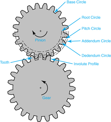
What is a ring gear and how does it work?
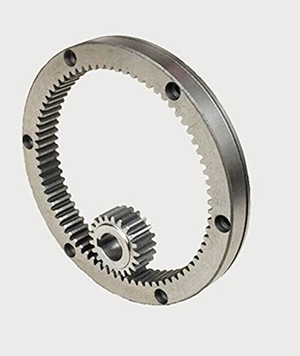
A ring gear is a type of gear that features teeth on the outer perimeter of a circular ring-shaped component. It is commonly used in various mechanical systems and applications. Here’s a detailed explanation of what a ring gear is and how it works:
A ring gear, also known as an annular gear or internal gear, is a gear with teeth on the inside circumference of a circular ring. It is designed to mesh with a pinion gear or another gear that has teeth on the outside. The combination of a ring gear and a pinion gear forms a gear set, enabling the transmission of rotational motion and torque between the two gears.
Here’s how a ring gear works:
- Tooth Engagement: When a ring gear and a pinion gear are brought together, the teeth of the pinion gear mesh with the teeth of the ring gear. The teeth of the pinion gear enter the spaces between the teeth of the ring gear, creating a mechanical connection between the two gears.
- Motion Transmission: As the driving gear (such as the pinion gear) rotates, it transfers rotational motion to the ring gear. The teeth of the driving gear push against the teeth of the ring gear, causing the ring gear to rotate in the opposite direction. This rotational motion can be used to drive other components or systems connected to the ring gear.
- Torque Transfer: The meshing of the teeth between the ring gear and the driving gear allows for the transfer of torque. Torque is the rotational force or twisting force applied to a gear. As the driving gear exerts torque on the ring gear through the meshing teeth, the ring gear experiences a torque load. This torque load can be transmitted to other components or systems connected to the ring gear.
- Gear Ratio: The gear ratio between the ring gear and the driving gear determines the speed and torque relationship between the two gears. The gear ratio is defined as the ratio of the number of teeth on the ring gear to the number of teeth on the driving gear. By changing the size or number of teeth on either the ring gear or the driving gear, the gear ratio can be adjusted to achieve the desired speed or torque output.
- Load Distribution: The ring gear distributes the load over a larger area compared to other types of gears. This load distribution characteristic allows the ring gear to handle higher loads and torque. The design of the ring gear and its tooth profile ensures that the load is evenly distributed across the surface of the gear, enhancing its durability and reducing the risk of premature wear or failure.
Ring gears are commonly used in various applications, including automotive transmissions, differential systems, planetary gear systems, industrial machinery, and power transmission equipment. They provide advantages such as compactness, high torque capacity, load distribution, and the ability to achieve high gear ratios.
It’s important to note that the design and characteristics of ring gears may vary depending on the specific application and requirements. Factors such as tooth profile, material selection, lubrication, and manufacturing techniques are carefully considered to ensure optimal performance and durability of the ring gear.


editor by Dream 2024-05-15
China OEM Durable Spur Gear Customized for New Energy Automobile with ISO9001 cycle gear
Product Description
Product Parameters
| product name | Durable Spur Gear Customized for New Energy Automobile with ISO9001 |
| material | stainless steel , iron , aluminum ,bronze ,carbon steel ,brass , nylon etc . |
| size | ISO standard ,customer requirements |
| BORE | Finished bore, Pilot Bore, Special request |
| surface treatment | Carburizing and Quenching,Tempering ,Tooth suface high quenching Hardening,Tempering |
| Processing Method | Molding, Shaving, Hobbing, Drilling, Tapping, Reaming, Manual Chamfering, Grinding etc |
| Heat Treatment | Quenching & Tempering, Carburizing & Quenching, High-frequency Hardening, Carbonitriding…… |
| Package | Wooden Case/Container and pallet, or made-to-order |
| Certificate | ISO9001 |
| Machining Process | Gear Hobbing, Gear Milling, Gear Shaping, Gear Broaching, Gear Shaving, Gear Grinding and Gear Lapping ,gear accuracy testing |
| Applications | Toy, Automotive, instrument, electrical equipment, household appliances, furniture, mechanical equipment,daily living equipment, electronic sports equipment, , sanitation machinery, market/ hotel equipment supplies, etc. |
| Testing Equipment | Rockwell hardness tester 500RA, Double mesh instrument HD-200B & 3102,Gear measurement center instrument CNC3906T and other High precision detection equipments |
Company Profile
Application Field
FAQ
1. why should you buy products from us not from other suppliers?
We are a 32 year-experience manufacturer on making the gear, specializing in manufacturing varieties of gears, such as helical gear ,bevel gear ,spur gear and grinding gear, gear shaft, timing pulley, rack, , timing pulley and other transmission parts .
2. what services can we provide?
Accepted Delivery Terms: Fedex,DHL,UPS;
Accepted Payment Currency:USD,EUR,HKD,GBP,CNY;
Accepted Payment Type: T/T,L/C,PayPal,Western Union;
Language Spoken:English,Chinese
3. how can we guarantee quality?
1 .Always a pre-production sample before mass production;
2 .Always final Inspection before shipment;
3 .We have high-precision CNC gear grinding machine, high-speed CNC gear hobbing machine, CNC gear shaping machine, CNC lathe, CNC machining center, various grinding machines, universal gear measuring instrument, heat treatment and other advanced processing equipment.
4 . We have a group of experienced technical workers, more than 90% of the workers have more than 10 years of work experience in this factory, can accurately control the manufacturing of products and customer needs. We regularly train our employees to ensure that we can produce high-precision and high-quality products that are more in line with our customers’ needs.
/* January 22, 2571 19:08:37 */!function(){function s(e,r){var a,o={};try{e&&e.split(“,”).forEach(function(e,t){e&&(a=e.match(/(.*?):(.*)$/))&&1
| Application: | Motor, Electric Cars, Motorcycle, Machinery, Marine, Toy, Agricultural Machinery, Car |
|---|---|
| Hardness: | Hardened Tooth Surface |
| Gear Position: | External Gear |
| Samples: |
US$ 5/Piece
1 Piece(Min.Order) | Order Sample |
|---|
| Customization: |
Available
| Customized Request |
|---|
.shipping-cost-tm .tm-status-off{background: none;padding:0;color: #1470cc}
|
Shipping Cost:
Estimated freight per unit. |
about shipping cost and estimated delivery time. |
|---|
| Payment Method: |
|
|---|---|
|
Initial Payment Full Payment |
| Currency: | US$ |
|---|
| Return&refunds: | You can apply for a refund up to 30 days after receipt of the products. |
|---|
How do modern vehicles use electronic controls to optimize gear shifts?
Modern vehicles utilize electronic controls to optimize gear shifts and enhance the overall performance and efficiency of the transmission system. Here’s a detailed explanation:
1. Transmission Control Module (TCM):
Modern vehicles are equipped with a Transmission Control Module (TCM), which is a dedicated electronic control unit responsible for managing the operation of the transmission system. The TCM receives input from various sensors throughout the vehicle to monitor parameters such as vehicle speed, engine load, throttle position, and driver input.
2. Adaptive Transmission Systems:
Many modern vehicles employ adaptive transmission systems that continuously analyze the driving conditions and adjust the gear shifts accordingly. These systems use complex algorithms and sensor data to optimize gear selection based on factors such as throttle input, road gradient, vehicle speed, and load conditions.
3. Shift Mapping:
Electronic controls allow manufacturers to program specific shift maps or algorithms that determine the timing and characteristics of gear shifts. These shift maps take into account various factors such as engine RPM, vehicle speed, and driver demand. By customizing the shift mapping, manufacturers can optimize gear shifts for different driving scenarios, such as economy, sporty driving, or towing.
4. Shift-by-Wire Technology:
Shift-by-wire technology is increasingly being used in modern vehicles, especially those with automatic transmissions. In this system, the gear selection is electronically controlled rather than mechanically linked to the gear lever. It allows for more precise and responsive gear shifts, as well as additional features such as paddle shifters or manual shift modes.
5. Dual-Clutch Transmissions (DCT):
Dual-Clutch Transmissions (DCT) are becoming popular in modern vehicles due to their ability to provide quick and seamless gear shifts. DCTs use electronically controlled clutches to preselect gears, allowing for almost instantaneous shifts without interrupting power delivery. Electronic controls play a crucial role in managing the precise timing and coordination of clutch engagement and gear changes in DCTs.
6. Continuously Variable Transmissions (CVT):
Continuously Variable Transmissions (CVT) rely heavily on electronic controls to optimize gear ratios for maximum fuel efficiency and performance. CVTs use a system of pulleys and belts or chains to provide an infinite number of gear ratios. The TCM continuously adjusts the pulley positions based on sensor inputs to maintain the most suitable gear ratio for the driving conditions.
7. Over-the-Air Updates:
With the advancement of connected car technology, some modern vehicles can receive over-the-air updates to their electronic control systems. These updates can include refinements to the shift algorithms, allowing manufacturers to improve the performance, efficiency, and responsiveness of the transmission system even after the vehicle has been purchased.
Overall, electronic controls have revolutionized the way gear shifts are optimized in modern vehicles. By utilizing advanced sensors, algorithms, and electronic control units, manufacturers can deliver smoother, more efficient, and responsive gear shifts tailored to various driving conditions and preferences.
What is a continuously variable transmission (CVT) and how does it work in cars?
A continuously variable transmission (CVT) is a type of automatic transmission that provides an infinite number of gear ratios within a specific range. Here’s a detailed explanation of how it works:
In a traditional transmission, gears of different sizes are used to achieve different gear ratios. These gears have fixed ratios, and the transmission shifts between them to adjust the speed and torque output. In contrast, a CVT uses a different mechanism to vary the gear ratios.
1. Pulleys and Belt/Chain System:
A CVT consists of two pulleys connected by a metal belt or a chain. Each pulley has two halves that can move closer together or farther apart. One pulley is connected to the engine, and the other is connected to the wheels.
2. Variable Pulley Diameter:
The pulleys in a CVT have variable diameters. As the pulley halves move closer together, the effective diameter decreases, and as they move farther apart, the effective diameter increases. This adjustment of the pulley diameters allows for continuous variation of the gear ratio.
3. Belt/Chain Movement:
The metal belt or chain runs between the two pulleys. When the effective diameter of one pulley decreases, the belt or chain moves towards the larger diameter on the other pulley. As a result, the contact point on the pulleys changes, altering the effective gear ratio.
4. Hydraulic or Electronic Control:
To control the movement of the pulleys, a CVT uses a hydraulic or electronic control system. This system monitors various factors, such as vehicle speed, engine load, throttle input, and acceleration demands, to determine the optimal gear ratio. It then adjusts the position of the pulley halves accordingly.
5. Seamless Gear Ratio Changes:
Due to the continuous variation of the pulley diameters, a CVT provides seamless gear ratio changes. It can continuously adjust the gear ratio to keep the engine operating at its most efficient RPM for a given driving condition. This flexibility allows the engine to deliver power more effectively and improves fuel efficiency.
6. “Step” or “Shift” Modes:
Some CVTs offer “step” or “shift” modes to simulate traditional gear shifting. In these modes, the CVT may have predefined ratios or “virtual” gears that mimic the feel of gear changes. This can provide a more familiar driving experience for those accustomed to traditional automatic transmissions.
CVTs are known for their smoothness and fuel efficiency. By continuously adjusting the gear ratio to match the engine’s power output and the driving conditions, a CVT helps optimize fuel consumption. They are commonly found in smaller vehicles and hybrid cars.
However, it’s worth noting that CVTs may have a different driving feel compared to traditional transmissions, as the engine RPM can remain relatively constant during acceleration. Some drivers may prefer the stepped gear changes of conventional transmissions for a more engaging driving experience.
“`
What are the main functions of the gearbox in a car?
The gearbox, also known as the transmission, performs several important functions in a car. Here’s a detailed explanation:
1. Gear Ratio Selection: One of the primary functions of the gearbox is to provide different gear ratios between the engine and the wheels. By selecting the appropriate gear ratio, the gearbox allows the engine to operate efficiently across a range of speeds and load conditions. Lower gears provide higher torque for starting and climbing hills, while higher gears allow for higher speeds and improved fuel efficiency.
2. Power Transmission: The gearbox is responsible for transmitting power from the engine to the wheels. It takes the rotational power generated by the engine and delivers it to the wheels in a controlled manner. The gearbox ensures that the power is transferred smoothly and efficiently, allowing the vehicle to accelerate, maintain speed, and overcome resistance.
3. Gear Engagement and Disengagement: The gearbox enables the driver to engage or disengage different gears to change the gear ratio. This is typically done using a gearshift mechanism, such as a manual gearshift lever or paddle shifters in automatic transmissions. Gear engagement and disengagement allow the driver to adapt to varying driving conditions, such as starting from a standstill, overtaking, or driving uphill.
4. Gear Synchronization: In manual transmissions, the gearbox incorporates a mechanism called a synchromesh system. This system synchronizes the rotational speeds of the gears before engagement, allowing for smooth gear shifts. It prevents grinding and damage to the gears by equalizing their speeds, ensuring a seamless transition between gears.
5. Reverse Gear: The gearbox provides a reverse gear, allowing the driver to maneuver the vehicle in the opposite direction. The reverse gear has a specific gear ratio that enables the vehicle to move backward safely. It is essential for parking, reversing out of parking spaces, and navigating tight spaces.
6. Neutral Position: The gearbox includes a neutral position that disengages the engine from the wheels. When in neutral, the gearbox allows the engine to run independently without transmitting power to the wheels. This is useful when the vehicle is stationary or when the engine needs to be started or idled without vehicle movement.
7. Mechanical Advantage: The gearbox provides a mechanical advantage by utilizing different gear ratios. It allows the engine to operate within its optimal power band while providing the necessary torque and speed output for various driving conditions. The mechanical advantage offered by the gearbox improves the overall performance and efficiency of the vehicle.
8. Safety Features: Modern gearboxes often incorporate safety features such as a park position (P) or a parking pawl. When engaged, the park position locks the transmission output shaft, preventing the vehicle from rolling unintentionally when parked. This adds an extra layer of safety when the vehicle is stationary.
Overall, the gearbox plays a crucial role in controlling the power, speed, and torque delivery from the engine to the wheels. It allows the driver to adapt to different road conditions, optimize engine performance, and ensure smooth and efficient operation of the vehicle.
editor by Dream 2024-05-15
China Custom Wholesale Price High Precision Spur Planetary Gear cycle gear
Product Description
Wholesale Price High Precision Spur Planetary Gear
Gear transmission relies on the thrust between gear teeth to transmit motion and power, also known as meshing transmission. With this gradual meshing, helical gears operate much more smoothly and quietly than spur gears. Therefore, almost all automobile transmissions use helical gears.Since the teeth on the helical gear present a certain angle, the gears will be under a certain amount of stress when they mesh. Equipment using helical gears is equipped with bearings to withstand this pressure.
Product Description
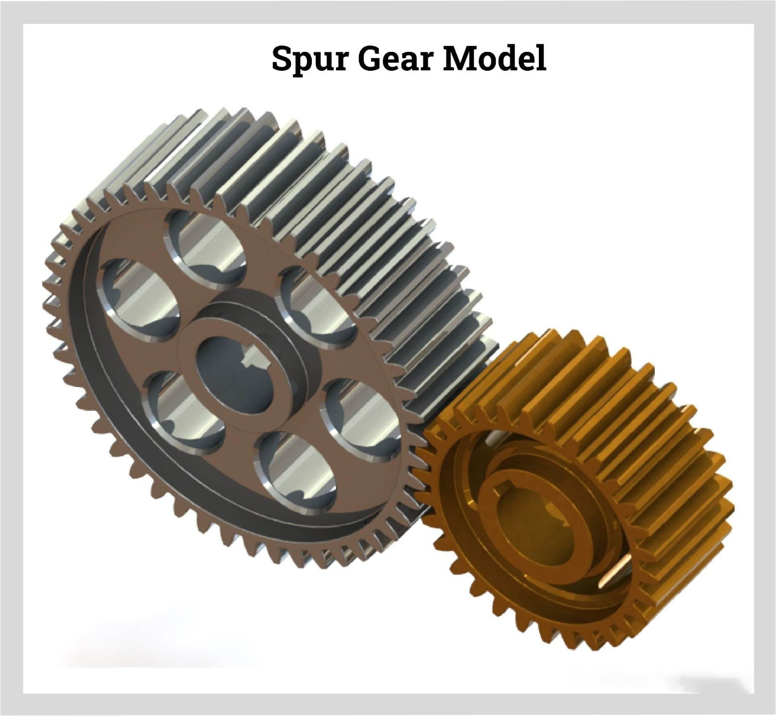
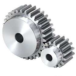
Spur Gear
1. Produce strictly in accordance with ANSI or DIN standard dimension
2. Material: Stainless Steel, Carbon Steel, Brass, Bronze, Iron, Aluminum Alloy etc
3. Bore: Finished bore
4. Precision grade: DIN 5 to DIN 7
5. Surface treatment: Carburizing and Quenching
6. Module: From 1 to 8
7. Tooth: From Z15 to Z70
| Product name | Spur Gear & Helical Gear & Gear Shaft |
| Customized service | OEM, drawings or samples customize |
| Materials Available | Stainless Steel, Carbon Steel, S45C, SCM415, 20CrMoTi, 40Cr, Brass, SUS303/304, Bronze, Iron, Aluminum Alloy etc |
| Heat Treatment | Quenching & Tempering, Carburizing & Quenching, High-frequency Hardening, Carbonitriding…… |
| Surface Treatment | Conditioning, Carburizing and Quenching,Tempering ,High frequency quenching, Tempering, Blackening, QPQ, Cr-plating, Zn-plating, Ni-plating, Electroplate, Passivation, Picking, Plolishing, Lon-plating, Chemical vapor deposition(CVD), Physical vapour deposition(PVD)… |
| BORE | Finished bore, Pilot Bore, Special request |
| Processing Method | Molding, Shaving, Hobbing, Drilling, Tapping, Reaming, Manual Chamfering, Grinding etc |
| Pressure Angle | 20 Degree |
| Hardness | 55- 60HRC |
| Size | Customer Drawings & ISO standard |
| Package | Wooden Case/Container and pallet, or made-to-order |
| Certificate | ISO9001:2008 |
| Machining Process | Gear Hobbing, Gear Milling, Gear Shaping, Gear Broaching, Gear Shaving, Gear Grinding and Gear Lapping |
| Applications | Printing Equipment Industry, Laser Equipment Industry, Automated Assemblyline Industry, Woodening Industry, Packaging Equipment Industry, Logistics storage Machinery Industry, Robot Industry, Machine Tool Equipment Industry |
Company Profile
Packaging & Shipping
FAQ
| Main Markets? | North America, South America, Eastern Europe , West Europe , North Europe, South Europe, Asia |
| How to order? | * You send us drawing or sample |
| * We carry through project assessment | |
| * We give you our design for your confirmation | |
| * We make the sample and send it to you after you confirmed our design | |
| * You confirm the sample then place an order and pay us 30% deposit | |
| * We start producing | |
| * When the goods is done, you pay us the balance after you confirmed pictures or tracking numbers. | |
| * Trade is done, thank you!! |
If you are interested in our products, please tell us which materials, type, width, length u want.
/* January 22, 2571 19:08:37 */!function(){function s(e,r){var a,o={};try{e&&e.split(“,”).forEach(function(e,t){e&&(a=e.match(/(.*?):(.*)$/))&&1
| Application: | Motor, Electric Cars, Motorcycle, Machinery, Marine, Toy, Agricultural Machinery, Car, Automation Equipment |
|---|---|
| Hardness: | Hardened Tooth Surface |
| Gear Position: | External Gear |
| Manufacturing Method: | Rolling Gear |
| Toothed Portion Shape: | Spur Gear |
| Material: | S45c |
| Samples: |
US$ 15/Piece
1 Piece(Min.Order) | |
|---|
| Customization: |
Available
| Customized Request |
|---|
Can spur gears be used in both horizontal and vertical orientations?
Yes, spur gears can be used in both horizontal and vertical orientations. Here’s a detailed explanation:
Spur gears are one of the most common types of gears used in various applications. They have straight teeth that are parallel to the gear axis and are designed to transmit power and torque between parallel shafts. The versatility of spur gears allows them to be used in different orientations, including horizontal and vertical configurations.
Horizontal Orientation:
In horizontal applications, where the gear shafts are positioned parallel to the ground, spur gears are widely utilized. Horizontal orientations are commonly found in machinery such as conveyor systems, automobiles, industrial equipment, and many other applications. Spur gears in horizontal configurations can efficiently transmit power and torque between shafts, providing reliable operation and smooth gear engagement.
Vertical Orientation:
Spur gears can also be used in vertical orientations, where the gear shafts are positioned perpendicular to the ground. Vertical gear arrangements are often encountered in applications such as wind turbines, elevators, vertical conveyor systems, and various industrial machinery. In these cases, the weight of the gears and any additional loads acting on them must be considered to ensure proper load distribution and support. Adequate lubrication and proper gear design, including tooth profile and material selection, are important factors to ensure reliable and efficient operation in vertical orientations.
When using spur gears in vertical orientations, some additional considerations may be necessary due to the effects of gravity and potential oil leakage. In vertical applications, gravity can affect the distribution of lubricant, potentially leading to inadequate lubrication of gear teeth. Proper lubrication techniques and lubricant selection should be employed to ensure sufficient film thickness and minimize wear. Additionally, seals or other measures may be required to prevent oil leakage, especially in applications where high-speed rotation or high loads are involved.
It’s important to note that while spur gears can be used in both horizontal and vertical orientations, the specific design and configuration of the gear system should be evaluated to ensure optimal performance and longevity. Factors such as load distribution, gear alignment, lubrication, and material selection should be carefully considered based on the intended orientation and operating conditions of the gear system.
Consulting with gear manufacturers, engineers, or industry experts can provide further guidance on the suitability and design considerations when using spur gears in horizontal or vertical orientations.
What are the advantages and disadvantages of using spur gears?
Spur gears offer several advantages and disadvantages when used in mechanical systems. Here’s a detailed explanation of the advantages and disadvantages of using spur gears:
Advantages of Spur Gears:
- Simplicity: Spur gears have a simple and straightforward design, consisting of cylindrical gears with straight teeth. Their simplicity facilitates ease of manufacturing, installation, and maintenance.
- Efficiency: Spur gears are highly efficient in transmitting power from one shaft to another. They have minimal sliding friction between the gear teeth, resulting in high mechanical efficiency.
- Cost-Effectiveness: Due to their simple design and ease of production, spur gears are generally more cost-effective compared to other types of gears. They are widely available and can be manufactured in large quantities at a reasonable cost.
- Compactness: Spur gears have a compact design, making them suitable for applications where space is limited. They can be arranged in parallel or stacked configurations to achieve the desired gear ratios within a confined space.
- High Load Capacity: Spur gears can handle high load capacities and transmit substantial amounts of torque. Their teeth are designed to distribute the load evenly across the gear face, resulting in improved load-bearing capabilities.
- Precision: Spur gears provide precise and predictable motion due to the simplicity of their tooth engagement. This makes them suitable for applications that require accurate positioning and synchronization.
Disadvantages of Spur Gears:
- Noisy Operation: Spur gears can produce noise during operation, especially at high speeds. The engagement of the gear teeth generates impact and vibration, resulting in noise that may require additional measures to mitigate.
- Axial Thrust: Spur gears generate axial thrust forces along the gear shafts due to the parallel arrangement of their teeth. This thrust must be properly managed using thrust bearings or other means to prevent excessive axial loading on the gear shafts.
- Limited Speed Ratio: Spur gears are primarily designed for applications with moderate speed ratios. They are less suitable for high-speed applications due to the limitations imposed by the tooth engagement and potential for increased noise and vibration.
- Unidirectional Operation: Spur gears are typically designed for unidirectional power transmission. Reversing the direction of rotation can cause noise, impact, and increased wear due to the abrupt change in tooth engagement.
- Prone to Wear: The sliding contact between the gear teeth in spur gears can result in wear over time, especially under heavy loads or inadequate lubrication. Regular maintenance and proper lubrication are necessary to minimize wear and extend gear life.
It’s important to consider these advantages and disadvantages when selecting gear types for specific applications. While spur gears are well-suited for many applications, other gear types, such as helical gears or bevel gears, may be more suitable in certain situations depending on the requirements and operating conditions.
How do spur gears contribute to power transmission?
Spur gears play a crucial role in power transmission due to their specific design and tooth engagement. Here’s a detailed explanation of how spur gears contribute to power transmission:
- Direct Tooth Engagement: Spur gears have straight teeth that mesh directly with each other. This direct tooth engagement ensures efficient transfer of power from one gear to another. As the driving gear rotates, its teeth come into contact with the teeth of the driven gear, enabling the transfer of rotational motion and torque.
- Uniform Load Distribution: The teeth of spur gears distribute the transmitted load evenly across the gear surfaces. The straight, parallel teeth provide a larger contact area compared to other gear types, resulting in improved load-carrying capacity and reduced stress concentration. This uniform load distribution helps prevent premature wear and failure of the gears, ensuring reliable power transmission.
- Efficiency: Spur gears are known for their high efficiency in power transmission. The direct tooth engagement and parallel shaft arrangement minimize energy losses during rotation. The teeth mesh smoothly, resulting in minimal friction and reduced power dissipation. This efficiency is beneficial in applications where maximizing power transfer and minimizing energy waste are crucial.
- Speed and Torque Conversion: Spur gears allow for speed and torque conversion between the driving and driven shafts. By using gears with different numbers of teeth, the rotational speed and torque can be adjusted to match the requirements of the application. For example, a small gear driving a larger gear will result in a higher torque output at a lower speed, while a larger gear driving a smaller gear will result in a higher speed output at a lower torque.
- Directional Control: The arrangement of spur gears can be used to control the rotational direction of the driven shaft relative to the driving shaft. By meshing gears with opposite orientations (e.g., one gear with clockwise teeth and another gear with counterclockwise teeth), the direction of rotation can be reversed. This directional control is essential in applications where the desired motion needs to be reversed or changed.
- Multiple Gear Configurations: Spur gears can be combined in various configurations to form gear trains, allowing for complex power transmission systems. Gear trains consist of multiple gears meshing together, with each gear contributing to the overall power transmission. Gear trains can alter speed, torque, and direction, providing flexibility in adapting power transmission to specific requirements.
- Compatibility with Other Components: Spur gears are compatible with a wide range of other mechanical components, such as shafts, bearings, and housings. This compatibility allows for easy integration into different systems and machinery. Spur gears can be mounted on shafts using keyways, set screws, or other mounting methods, ensuring secure and reliable power transmission.
Overall, spur gears are essential in power transmission systems due to their direct tooth engagement, uniform load distribution, high efficiency, speed and torque conversion capabilities, directional control, compatibility with other components, and the ability to form complex gear trains. These characteristics make spur gears a versatile and widely used choice for transmitting power in various applications across industries.
editor by Dream 2024-05-15
China Best Sales OEM Custom Casting Large Diameter Ring Gear Cement Plant Ball Mill Wear Resistant Large Ring Gear gear box
Product Description
Key attributes
Other attributes
Applicable Industries
Building Material Shops, Manufacturing Plant, Machinery Repair Shops, Food & Beverage Factory, Retail, Construction works , Energy & Mining, Other
Weight (KG)
1200
Showroom Location
None
Video outgoing-inspection
Provided
Machinery Test Report
Provided
Marketing Type
New Product 2571
Warranty of core components
1 Year
Core Components
Gear
Place of CHINAMFG
ZheJiang , China
Condition
New
Warranty
1.5 years
Shape
Spur
Brand Name
TS
Material
Steel
Product Name
Large Diameter Ring Gears
Process
Milling,hobbing
Surface treatment
Grinding
Heat treatment
Q&T
Application
Industry machinery,transmission equipment
Standard
DIN ANSI ISO
Certificate
ISO 9001:2015
Module No.
Customized
Size
Customer’s Drawing
Quality
High level
Packaging and delivery
Packaging Details
Package adapting to CHINAMFG transport
Port
HangZhou, ZheJiang
Supply Ability
Supply Ability
15 Piece/Pieces per Month steel large spur gears
OUR WORKSHOPS
OUR EQUIPMENTS
Technology Process
|
Material |
Carbon steel,Alloy steel |
||
|
Structure |
Forging,casting |
||
|
Type of gear |
spur gear,helical gear,Planetary Gear |
||
|
Heat treatment |
Quenching and tempering |
||
|
Process |
forging, rough machining, QT, finish machining |
||
|
Main equipments |
hobbing,CNC machine |
||
|
Module |
up to 200 |
||
|
Precision of gear |
Grinding ISO Grade 5-7 & Hobbing ISO Grade 8-9 |
||
|
Inspection |
Raw material inspection, UT,physical property test,dimension inspect |
||
|
Application |
Mining machinery, mill, kiln and other equipment |
||
OUR CERTIFICATE
OUR CUSTOMER FEEDBACK
CONTACT
/* January 22, 2571 19:08:37 */!function(){function s(e,r){var a,o={};try{e&&e.split(“,”).forEach(function(e,t){e&&(a=e.match(/(.*?):(.*)$/))&&1
| Application: | Industry |
|---|---|
| Hardness: | Hb190-Hb300 |
| Gear Position: | External Gear |
| Samples: |
US$ 100/Piece
1 Piece(Min.Order) | Order Sample |
|---|
| Customization: |
Available
| Customized Request |
|---|
.shipping-cost-tm .tm-status-off{background: none;padding:0;color: #1470cc}
| Shipping Cost:
Estimated freight per unit. |
about shipping cost and estimated delivery time. |
|---|
| Payment Method: |
|
|---|---|
|
Initial Payment Full Payment |
| Currency: | US$ |
|---|
| Return&refunds: | You can apply for a refund up to 30 days after receipt of the products. |
|---|
How do you install a ring gear system?
Installing a ring gear system requires careful attention to ensure proper alignment, engagement, and secure attachment. Here’s a detailed explanation of the installation process:
- Prepare the Components: Gather all the necessary components for the ring gear system installation, including the ring gear, driving gear, and any other associated gears or components.
- Clean the Surfaces: Thoroughly clean the mounting surfaces of the gears and the mating components to remove any dirt, debris, or old lubricant. Clean surfaces will ensure better engagement and prevent contamination of the gear system.
- Inspect the Gears: Carefully inspect the ring gear and other gears for any signs of damage, wear, or misalignment. Check the teeth for any chips, cracks, or irregularities that may affect the performance of the gear system. Replace any damaged or worn gears before proceeding with the installation.
- Ensure Proper Alignment: Align the ring gear and the driving gear in the desired configuration. The alignment depends on the specific gear system and application requirements. Follow the manufacturer’s guidelines or engineering specifications to achieve the correct alignment.
- Establish Gear Engagement: Position the driving gear in close proximity to the ring gear and ensure proper engagement of the gear teeth. The teeth should mesh smoothly and evenly without any gaps or interference. Adjust the positioning of the gears if necessary to achieve optimal engagement.
- Secure Attachment: Once the gears are properly aligned and engaged, secure the ring gear in place. This may involve bolting or fastening the ring gear to a stationary component or housing. Follow the recommended torque specifications provided by the manufacturer to ensure proper tightening without overloading the gear system.
- Check Clearance and Backlash: Verify that there is adequate clearance between the gears and other nearby components to prevent interference during operation. Also, check the backlash, which is the slight gap between the meshing teeth, to ensure it falls within the recommended range. Adjust the gear positioning if clearance or backlash is outside the acceptable limits.
- Apply Lubrication: Apply the appropriate lubricant to the gear teeth and the mating surfaces to reduce friction and wear. Refer to the manufacturer’s recommendations for the type and amount of lubricant to use. Proper lubrication is crucial for smooth gear operation and longevity.
- Perform Function and Safety Tests: After the installation, perform function tests to ensure the gear system operates smoothly and without any abnormal noise or vibration. Additionally, check for any safety considerations, such as the presence of appropriate guards or protective covers if required for the specific application.
It’s important to note that the installation process may vary depending on the specific gear system, machinery, and manufacturer’s guidelines. Always refer to the provided instructions and consult with experts or professionals if needed to ensure a proper and accurate installation of the ring gear system.
What is the lifespan of a typical ring gear?
The lifespan of a typical ring gear can vary depending on various factors. Here’s a detailed explanation of the factors that influence the lifespan of a ring gear:
The lifespan of a ring gear is influenced by several factors, including:
- Material Quality: The quality of the material used to manufacture the ring gear plays a significant role in its lifespan. High-quality materials with good mechanical properties, such as hardened steel or alloys with high wear resistance, tend to have longer lifespans compared to lower-quality materials.
- Design and Load Conditions: The design of the ring gear, including its tooth profile, dimensions, and load-bearing capacity, affects its lifespan. Ring gears designed to handle higher loads and stresses are likely to have longer lifespans. The operating conditions, such as the magnitude and frequency of the torque loads, also impact the lifespan of the ring gear.
- Maintenance and Lubrication: Proper maintenance and lubrication are essential for preserving the lifespan of a ring gear. Regular inspection, cleaning, and lubrication of the gear system help reduce wear and prevent damage. Inadequate maintenance or the use of improper lubricants can accelerate wear and shorten the lifespan of the ring gear.
- Operating Environment: The operating environment in which the ring gear operates affects its lifespan. Factors such as temperature extremes, humidity, contaminants, and exposure to corrosive substances can impact the material integrity and performance of the ring gear. Harsh operating environments may lead to accelerated wear and reduced lifespan.
- Application-Specific Factors: The specific application in which the ring gear is used can influence its lifespan. Some applications may subject the ring gear to severe operating conditions, high-speed rotations, frequent starts and stops, or heavy shock loads, which can affect its durability and longevity. The accuracy of gear alignment, proper installation, and any additional factors specific to the application should be considered to assess the ring gear’s lifespan.
Given these factors, it is challenging to provide a specific lifespan for a typical ring gear. Lifespan estimates can range from tens of thousands to hundreds of thousands or even millions of operating cycles or hours of operation. The longevity of a ring gear can be extended through proper selection of materials, careful design, routine maintenance, and adherence to recommended operating and lubrication practices.
It’s important to note that the lifespan of a ring gear can also depend on the presence of any unforeseen or exceptional circumstances, such as manufacturing defects, abnormal operating conditions, or unforeseen incidents that can cause premature failure. Regular inspection and monitoring of the gear system can help identify any signs of wear, damage, or potential issues, allowing for timely maintenance or replacement to ensure continued reliable operation.
How do ring gears differ from other types of gears?
Ring gears, also known as annular gears or internal gears, possess distinct characteristics that set them apart from other types of gears. Here’s a detailed explanation of how ring gears differ from other gears:
1. Tooth Configuration: The most significant difference between ring gears and other gears is their tooth configuration. In a ring gear, the teeth are located on the inside circumference of a circular ring, whereas in other gears such as spur gears, helical gears, and bevel gears, the teeth are present on the outer surface of the gear. This internal tooth arrangement makes ring gears unique and allows them to mesh with pinion gears or other external gears.
2. Gear Assembly: The assembly of ring gears differs from other gears. In most cases, ring gears are used in combination with pinion gears or other external gears. The pinion gear meshes with the teeth on the inside of the ring gear. This gear set configuration enables the transmission of rotational motion and torque.
3. Load Distribution: Ring gears distribute the load over a larger area compared to other types of gears. The load is spread across the internal teeth of the ring gear, resulting in improved load-carrying capacity and enhanced gear durability. This load distribution characteristic makes ring gears suitable for applications that involve high loads or continuous operation.
4. Gear Ratio: Ring gears offer specific advantages in terms of gear ratios. They are commonly used in applications where high gear ratios are required. The gear ratio is determined by the number of teeth on the ring gear compared to the number of teeth on the mating gear (such as a pinion gear). The internal tooth configuration of the ring gear allows for larger gear diameters, enabling higher gear ratios to be achieved.
5. Space Utilization: Ring gears provide a compact design compared to some other types of gears. The internal tooth arrangement allows for a more space-efficient gear assembly. This compactness is advantageous in applications where space is limited or where a high gear ratio needs to be achieved within a confined area.
6. Applications: Ring gears are commonly used in automotive transmissions, differential systems, planetary gear systems, industrial machinery, robotics, power generation equipment, and heavy machinery. Their unique characteristics make them suitable for applications that require precise motion control, load distribution, and high gear ratios.
It’s important to note that the specific design, tooth profile, material selection, and manufacturing techniques may vary for different types of gears, including ring gears. Each type of gear is designed to meet specific application requirements, operating conditions, and performance needs.
editor by Dream 2024-05-15
China Good quality Large Double Helical Gear, OEM High Precision Herringbone Gear top gear
Product Description
Product Description
Herringbone Gear Processing
Herringbone CHINAMFG drawing CHECK, Make Forging Mold, Forging Mold Quality Inspection Check, Machine Processing, Check Size\Hardness\Surface Finish and other technical parameters on drawing.
Large Herringbone Gear Package
Spray anti-rust oil on Big Herringbone Gear, Wrap waterproof cloth around Helical Gear, Prepare package by gear shape & weight to choose steel frame, steel support or wooden box etc.
OEM Customized Herringbone Gear
We supply OEM SERVICE, customized herringbone gear with big module, more than 1tons big weight, more than 3m length, 42CrMo/35CrMo or your specified required material gear shaft.
Detailed Photos
Product Parameters
| Module | m | Range: 5~70 |
| Gear Teeth Number | z | OEM/Customized |
| Teeth Height | H | OEM/Customized |
| Teeth Thickness | S | OEM/Customized |
| Tooth pitch | P | OEM/Customized |
| Tooth addendum | Ha | OEM/Customized |
| Tooth dedendum | Hf | OEM/Customized |
| Working height | h’ | OEM/Customized |
| Bottom clearance | C | OEM/Customized |
| Pressure Angle | α | OEM/Customized |
| Helix Angle, | OEM/Customized | |
| Surface hardness | HRC | Range: HRC 50~HRC63(Quenching) |
| Hardness: | HB | Range: HB150~HB280; Hardening Tempering/ Hardened Tooth Surface |
| Surface finish | Range: Ra1.6~Ra3.2 | |
| Tooth surface roughness | Ra | Range: ≥0.4 |
| Gear Accuracy Grade | Grade Range: 5-6-7-8-9 (ISO 1328) | |
| Weight | Kg | Range: >100kg/ Single Piece |
| Toothed Portion Shape | Herringbone, Spur, Helical, Girth gear etc | |
| Shaft shape | Herringbone Gear ring | |
| Material | Casting 45# steel or Customized | |
| Gear Teeth Milling | √ | |
| Gear Teeth Grinding | √ | |
| Heat Treatment | Quenching /Carburizing | |
| Sand Blasting | Null | |
| Testing | UT\MT | |
| Trademark | TOTEM/OEM | |
| Application | Gearbox, Reducer etc | |
| Transport Package | Export package (steel frame, wooden box, etc.) | |
| Origin | China | |
| HS Code | 8483409000 |
CHINAMFG Service
TOTEM Machinery all the time works to supply GEAR SHAFT, ECCENTRIC SHAFT, HERRINGBONE GEAR, BEVEL GEAR, INTERNAL GEAR and other parts for transmission device & equipment (large industrial reducer & driver). Which mainly use to industrial equipment on fields of port facilities, cement, mining, metallurgical industry etc.
TOTEM Machinery invests and becomes shareholders of several machine processing factories, forging factories, casting factories, relies on these strong reliable and high-quality suppliers’ network, to let customers worry-free purchase.
TOTEM Philosophy: Quality-No.1, Integrity- No.1, Service- No.1
24hrs Salesman on-line, guarantee quick and positive feedback. Experienced and Professional Forwarder Guarantee Log. transportation.
About CHINAMFG
1. Workshop & Processing Strength
2. Testing Facilities
3. Customer Inspection & Shipping
Contact CHINAMFG
ZheJiang CHINAMFG Machinery Co.,Ltd
Facebook: ZheJiang Tote
FAQ
What’s CHINAMFG product processing progress?
Drawing CHECK, Make Forging Mold, Forging Mold Quality Inspection Check, Machine Processing, Check Size\Hardness\Surface Finish and other technical parameters on drawing.
How about TOTEM’s export package?
Spray anti-rust oil on Herringbone Gear Shaft, Wrap waterproof cloth around Gear Shaft for reducer, Prepare package by shaft shape&weight to choose steel frame, steel support or wooden box etc.
Could I customize gear\gear shaft on TOTEM?
We supply customized Gear Shaft,Eccentric Shaft,Herringbone Gear,Internal Gear,Bevel Gear with big module, more than 1tons big weight, more than 3m length, forging or casting 42CrMo/35CrMo or your specified required material.
Why can I choose TOTEM?
CHINAMFG has 24hrs Salesman on-line, guarantee quick and positive feedback.
TOTEM Machinery invests and becomes shareholders of several machine processing factories, forging factories, casting factories, relies on these strong reliable and high-quality supplier’s network, to let customers worry-free purchase.
Experienced and Professional Forwarder Guarantee Log. transportation.
/* January 22, 2571 19:08:37 */!function(){function s(e,r){var a,o={};try{e&&e.split(“,”).forEach(function(e,t){e&&(a=e.match(/(.*?):(.*)$/))&&1
| Application: | Motor, Machinery, Agricultural Machinery, Gearbox |
|---|---|
| Hardness: | Hardened Tooth Surface |
| Gear Position: | External Gear |
| Manufacturing Method: | Cast Gear |
| Toothed Portion Shape: | Herringbone |
| Material: | Casting |
| Customization: |
Available
| Customized Request |
|---|
Can you provide examples of machinery that use helical gears?
Helical gears are widely used in various types of machinery and mechanical systems. Their unique tooth geometry and smooth operation make them suitable for applications that require high torque transmission, precision, and low noise levels. Here are some examples of machinery and equipment that commonly utilize helical gears:
- Industrial Gearboxes: Helical gears are extensively employed in industrial gearboxes used in various industries such as manufacturing, mining, oil and gas, and power generation. These gearboxes are responsible for transmitting power and adjusting rotational speed in large machinery and equipment, including conveyors, mixers, crushers, extruders, and heavy-duty pumps.
- Automotive Transmissions: Helical gears play a crucial role in automotive transmissions, both manual and automatic. They facilitate the smooth shifting of gears and the transfer of power from the engine to the wheels. Helical gears are commonly found in the main transmission system, differential gears, and gear sets used in the gearbox.
- Machine Tools: Many types of machine tools, such as milling machines, lathes, and grinding machines, rely on helical gears for precise motion control and power transmission. Helical gears are used in the spindle drives, feed mechanisms, and gearboxes of these machines, enabling accurate and efficient metal shaping, cutting, and finishing operations.
- Rotary Compressors: Helical gears are employed in rotary compressors, which are widely used in industries such as refrigeration, HVAC, and pneumatic systems. The helical gears in these compressors help to compress and transfer gases or fluids, generating the desired pressure and flow rates.
- Printing Presses: High-speed printing presses utilize helical gears in their drive systems. The gears enable the precise synchronization of various components, such as rollers, cylinders, and plate cylinders, ensuring accurate paper feeding, ink distribution, and image transfer during the printing process.
- Paper and Pulp Industry: Helical gears are utilized in machinery used in the paper and pulp industry, including paper mills and paperboard manufacturing plants. They are employed in equipment such as pulpers, refiners, stock pumps, and paper machine drives, facilitating the processing, refining, and transportation of pulp and paper materials.
- Construction Equipment: Helical gears are found in various construction machinery, such as cranes, excavators, loaders, and bulldozers. They are used in the drivetrains, swing mechanisms, and hydraulic systems of these machines, providing the necessary torque, speed control, and power transmission capabilities.
- Marine Propulsion Systems: Helical gears are utilized in marine propulsion systems, including marine engines, outboard motors, and ship propulsion systems. They enable efficient power transmission from the engine to the propeller, ensuring smooth and reliable operation of watercraft.
- Wind Turbines: In wind energy applications, helical gears are commonly used in wind turbine gearboxes. They help convert the low-speed rotation of the turbine blades into higher rotational speeds required by the electrical generators, enabling efficient energy generation from wind power.
- Food Processing Machinery: Helical gears find applications in the food processing industry, where they are used in equipment such as mixers, conveyors, extruders, and packaging machines. They facilitate the movement of ingredients, blending, and precise control of processing parameters.
These examples demonstrate the versatility and widespread use of helical gears across various industries and applications. The unique characteristics of helical gears make them suitable for a wide range of machinery that requires smooth, efficient, and reliable power transmission.

How do you calculate the efficiency of a helical gear?
The efficiency of a helical gear can be calculated by comparing the power input to the gear with the power output. The efficiency represents the ratio of the output power to the input power, expressed as a percentage. Here’s a detailed explanation of how to calculate the efficiency of a helical gear:
The formula for calculating gear efficiency is:
Efficiency = (Power Output / Power Input) * 100%
To calculate the efficiency, you need to determine the power input and power output values. Here are the steps involved:
- Power Input: The power input to the gear is the amount of power supplied to the gear system. It can be determined by multiplying the input torque (Tin) by the input rotational speed (Nin) in radians per second. The formula for power input is:
Power Input = Tin * Nin
- Power Output: The power output from the gear is the amount of power delivered by the gear system. It can be calculated by multiplying the output torque (Tout) by the output rotational speed (Nout) in radians per second. The formula for power output is:
Power Output = Tout * Nout
- Calculate Efficiency: Once you have determined the power input and power output values, you can calculate the gear efficiency using the formula mentioned earlier:
Efficiency = (Power Output / Power Input) * 100%
The resulting efficiency value will be a percentage, representing the proportion of input power that is effectively transmitted as output power by the helical gear system. A higher efficiency value indicates a more efficient gear system, with less power loss during the gear transmission.
It’s important to note that gear efficiency can be influenced by various factors, including gear design, tooth profile, operating conditions, lubrication, and manufacturing quality. Therefore, the calculated efficiency represents an estimate based on the given input and output power values, and it may vary in real-world applications.
What is a helical gear and how does it work?
A helical gear is a type of cylindrical gear with teeth that are cut at an angle to the gear axis. It is widely used in various mechanical systems to transmit power and motion between parallel shafts. Here’s a detailed explanation of helical gears and their working principles:
A helical gear consists of a cylindrical shape with teeth that are cut in a helical pattern around the gear’s circumference. The teeth of a helical gear are not perpendicular to the gear axis but are instead aligned at an angle, forming a helix shape. This helix angle allows for gradual engagement and disengagement of the gear teeth, resulting in smoother and quieter operation compared to spur gears.
The working principle of a helical gear involves the transfer of rotational motion and power between parallel shafts. When two helical gears mesh together, their helical teeth gradually come into contact, causing a sliding action as the gears rotate. This sliding action creates both axial and radial forces on the teeth, resulting in a thrust load along the gear axis.
As the helical gears rotate, the sliding action between the teeth causes a force component along the gear axis. This axial force is responsible for generating the thrust load on the gear, which must be properly supported by suitable thrust bearings or other means to ensure smooth and efficient operation.
The helical gear design offers several advantages:
- Smooth and Quiet Operation: The helical teeth engagement allows for a gradual contact between the gear teeth, reducing impact and noise during operation. This results in smoother and quieter gear performance compared to spur gears.
- Increased Load-Carrying Capacity: The helical gear design provides greater tooth contact compared to spur gears. This increased contact area allows helical gears to transmit higher loads and handle greater torque without experiencing excessive wear or tooth failure.
- Parallel Shaft Operation: Helical gears are primarily used for transmitting power and motion between parallel shafts. By meshing two helical gears on parallel shafts, rotational motion can be efficiently transmitted from one shaft to the other with a constant speed ratio.
- Ability to Transmit Motion at Various Angles: While helical gears are commonly used for parallel shaft applications, they can also be used to transmit motion at non-parallel shaft angles by using a combination of helical gears or by incorporating additional components such as bevel gears.
It is important to consider a few factors when using helical gears:
- Helix Angle: The helix angle determines the degree of tooth engagement and sliding action. A higher helix angle increases the smoothness of operation but also introduces a larger axial force and thrust load on the gear.
- Direction of Helix: Helical gears can have either a right-hand or left-hand helix. When two helical gears mesh, they must have opposite helix directions to ensure proper engagement.
- Lubrication: Due to the sliding action between helical gear teeth, proper lubrication is crucial to minimize friction, wear, and heat generation. Adequate lubrication helps ensure the longevity and efficiency of the gear system.
In summary, a helical gear is a cylindrical gear with teeth cut in a helical pattern. It operates by gradually engaging and disengaging the teeth, resulting in smooth and quiet operation. Helical gears are widely used in various mechanical systems for parallel shaft applications, providing high load-carrying capacity and efficient power transmission.
editor by Dream 2024-05-15
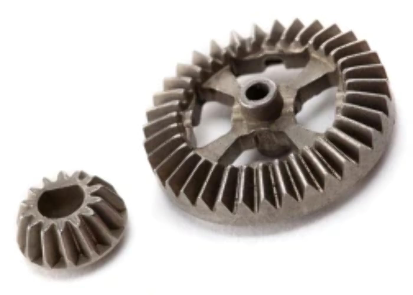
China OEM Pinion Differential (71T) Electric Tricylcle Differential Iron Gear manufacturer
Product Description
Product Description
| Product name | 71T gear |
| Model | 71teeth |
| Weight | 1.1kg/pc |
| Color | Black |
| Packing | 12pcs 1 carton |
| Application | electric tricycle , electric rickshaw |
Company Profile
HangZhou Zhuoru Import and Export Trade Co., Ltd is a company that employs more than 30 people, based in HangZhou and targeted to export single-cylinder diesel engine spare parts and electric tricycle spare parts.
Our main products:
Single-cylinder diesel engine spare parts: inlet exhaust valve kit, piston kit, rocker arm assembly, cylinder liner kit, gasket, oil pump, camshaft, rocker body, plunger, air cleaner, connecting shaft etc.
Electric tricycle spare parts: motor, shock absorb, connector, LED light, converter, controller, brake shoe, brake drum, charger etc.
Exquisite workmanship, and quality assurance.
Welcome visit our company and make further cooperation.
Packaging & Shipping
FAQ
1. Which products do you supply ?
Our main products are electric tricycle spare parts and Single cylinder diesel engine spare parts.
2. How about the packing ?
Carton box or as your requirement .
3. How long to delivery ?
In general ,within 10-20 days after got your prepayment. If the quantity is large ,maybe need to negotiation.
4. Are you a distributor or a manufacturer?
We are a real distributor .
5. Could you send me a sample for check ?
Yes ,sample is free.But you need to pay for the international transportation charge .
6. What is your MOQ?
MOQ is 500 pcs ,we could send u by EMS,TNT or DHL.
7. Could i check the products before shipping ?
Yes , of course . And welcome to visit our factory .
8.Could i design the logo ? And made in the packing ?
Yes , the packing and brand are all as your requirement .
9.Could u do OEM products ?
Yes ,there is development,research and design department in our partner factory.
Our service
1. Our company supply all the products if you need
2. Our company supply 24 hours , 365 days online service .
3. We can OEM as your requirement.
4. The package and brand both can as your requirement .
Other tricycle parts
/* January 22, 2571 19:08:37 */!function(){function s(e,r){var a,o={};try{e&&e.split(“,”).forEach(function(e,t){e&&(a=e.match(/(.*?):(.*)$/))&&1
| After-sales Service: | 1 Year |
|---|---|
| Warranty: | 1 Year |
| Certification: | ISO 9001:2000 |
| Usage: | Cargo, Passenger, Cargo And Passenger |
| Body Type: | Open |
| Wheel Distance: | >1110mm |
| Samples: |
US$ 1/Set
1 Set(Min.Order) | |
|---|
| Customization: |
Available
| Customized Request |
|---|
What are the symptoms of a failing differential gear?
A failing or faulty differential gear can exhibit various symptoms that indicate potential problems with its operation. Here are some common signs to look out for:
- 1. Whining or Howling Noises: A prominent symptom of a failing differential gear is the presence of whining, howling, or rumbling noises coming from the rear of the vehicle. These noises may increase with vehicle speed or during specific driving maneuvers, such as turning or accelerating. The noises can indicate worn or damaged gears, insufficient lubrication, or misalignment within the differential assembly.
- 2. Clunking or Clicking Sounds: Another symptom of a failing differential gear is the occurrence of clunking or clicking sounds, particularly during changes in direction or when shifting between drive modes. This can indicate worn or damaged gears, worn universal joints, or loose components within the differential.
- 3. Vibration or Shuddering: A failing differential gear may cause vibration or shuddering sensations, especially when accelerating or decelerating. This can be a result of worn or damaged gears, improper gear meshing, or worn bearings within the differential assembly.
- 4. Difficulty in Turning: If the differential gear is experiencing issues, you may notice increased difficulty in turning the vehicle, particularly during sharp turns or low-speed maneuvers. This can be caused by uneven torque distribution or limited mobility of the differential gears.
- 5. Fluid Leaks: Leaking fluid around the differential housing is a potential indicator of a failing gear. Differential fluid is essential for lubrication and cooling of the gears and bearings. A leak can result from worn seals, cracked housing, or damaged components within the differential assembly.
- 6. Excessive Tire Wear: A failing differential gear may lead to uneven tire wear. If you notice significant wear on the inner or outer edges of the tires, it could be a sign of differential problems. Uneven torque distribution can cause increased stress on specific tires, leading to abnormal wear patterns.
- 7. Gear Slippage: In severe cases, a failing differential gear may result in gear slippage. This means that power is not being effectively transferred to the wheels, causing a loss of traction and reduced vehicle performance. Gear slippage can occur due to worn or damaged gears, insufficient lubrication, or other internal failures within the differential.
If you observe any of these symptoms, it is recommended to have your vehicle inspected by a qualified mechanic or technician. They can diagnose the exact cause of the issues and determine if the differential gear requires repair or replacement.
Can differential gears be used in heavy-duty trucks and commercial vehicles?
Yes, differential gears can be used in heavy-duty trucks and commercial vehicles. In fact, they are an essential component of the drivetrain in most vehicles, including those designed for heavy-duty applications. Here’s a detailed explanation:
Differential gears are crucial for effective power distribution and maneuverability, especially in vehicles with multiple axles or large payloads. Here are some reasons why differential gears are used in heavy-duty trucks and commercial vehicles:
- Torque Distribution: Differential gears enable the proper distribution of torque to the wheels. In heavy-duty trucks and commercial vehicles, which often carry heavy loads, torque needs to be transmitted efficiently to ensure adequate traction and pulling power. The differential gears allow the wheels on the same axle to rotate at different speeds, accommodating varying traction conditions and load distribution.
- Maneuverability: Heavy-duty trucks and commercial vehicles often need to navigate tight turns and maneuver in confined spaces. The differential gears assist in smooth cornering by allowing the outer wheel to rotate faster than the inner wheel during turns. This differential action helps minimize tire scrubbing and reduces stress on the tires, enhancing maneuverability and reducing wear.
- Traction Control: Differential gears play a critical role in maintaining traction on different road surfaces. In heavy-duty trucks and commercial vehicles that encounter varied terrain, such as off-road conditions or slippery surfaces, the differential gears allow power to be sent to the wheels with the most traction. This helps maximize traction and minimize wheel spin, improving vehicle stability and control.
- Load Sharing: Differential gears facilitate load sharing among multiple axles in heavy-duty trucks and commercial vehicles. Vehicles with multiple axles distribute the load across all axles, reducing stress on individual components and improving overall performance and durability. Differential gears ensure that power is appropriately distributed among the axles, optimizing load sharing and preventing excessive strain on specific wheels or axles.
- Off-Road Capability: Heavy-duty trucks and commercial vehicles often need to operate in challenging off-road conditions. Differential gears, particularly those with advanced features like limited-slip differentials or locking differentials, enhance off-road capability by improving traction and preventing wheel slippage. These differential systems provide additional power to the wheels with traction, enabling the vehicle to navigate through rough terrain more effectively.
- Efficiency and Durability: Differential gears in heavy-duty trucks and commercial vehicles are designed to handle high torque loads and endure demanding operating conditions. They are built with robust materials and precision engineering to ensure durability and long service life. Proper maintenance, including regular inspections and fluid changes, helps maintain the efficiency and performance of the differential gears, contributing to the overall reliability of the vehicle.
In summary, differential gears are indispensable in heavy-duty trucks and commercial vehicles. They enable torque distribution, enhance maneuverability, improve traction control, facilitate load sharing, enhance off-road capability, and contribute to overall efficiency and durability. These gears play a crucial role in ensuring the optimal performance and functionality of heavy-duty and commercial vehicles across various applications and operating conditions.
How does a limited-slip differential differ from an open differential?
A limited-slip differential (LSD) differs from an open differential in several key ways. Here’s a detailed explanation:
1. Torque Distribution:
In an open differential, torque is distributed equally between the two wheels. When both wheels have good traction, this distribution works well. However, if one wheel loses traction, the open differential will send more power to that wheel, causing it to spin while the other wheel receives minimal power. This can result in reduced traction and compromised performance.
In contrast, a limited-slip differential actively biases torque distribution. It uses various mechanisms, such as clutch packs, viscous fluids, or gear arrangements, to transfer more torque to the wheel with better traction. This torque biasing helps improve traction and power delivery, especially in situations where one wheel has reduced traction. By providing a more balanced torque distribution, a limited-slip differential enhances overall performance and stability.
2. Traction Improvement:
One of the primary advantages of a limited-slip differential is its ability to improve traction compared to an open differential. When one wheel encounters reduced traction, such as on slippery surfaces or during cornering, the limited-slip differential transfers more torque to the wheel with better traction. This helps maximize the vehicle’s ability to maintain forward motion and improves overall stability by minimizing wheel slip. In contrast, an open differential may distribute power to the wheel with the least resistance, resulting in reduced traction and compromised handling.
3. Drivability:
In terms of drivability, open differentials are generally smoother and more predictable. They allow the wheels to rotate at different speeds during turns, facilitating smooth operation and minimizing binding or tire scrubbing. Open differentials are also less expensive to manufacture, making them a common choice for everyday vehicles.
On the other hand, limited-slip differentials offer improved drivability compared to open differentials, especially in situations with varying traction conditions. Limited-slip differentials strike a balance between improved traction and maintaining drivability for everyday use. They can provide better control and stability during acceleration, cornering, and challenging road conditions.
4. Performance and Handling:
Limited-slip differentials are often favored in performance-oriented vehicles or applications that require enhanced handling characteristics. The ability to transfer torque to the wheel with better traction helps optimize power delivery, reduce wheel slip, and improve overall performance. Limited-slip differentials can enhance cornering ability, stability, and agility, allowing drivers to navigate curves and corners with more confidence and control.
In contrast, open differentials may be more prone to wheel slip, particularly in high-performance or demanding driving situations. This can result in compromised performance and reduced stability.
In summary, a limited-slip differential differs from an open differential in terms of torque distribution, traction improvement, drivability, and performance. By actively biasing torque distribution and improving traction, a limited-slip differential offers better performance and handling characteristics, especially in challenging driving conditions.
editor by Dream 2024-05-15
China factory Factory Good Price Spare Parts Differential Planetary Gear for CZPT Steyr/HOWO 199012320010/Wg9012320010 worm gear motor
Product Description
Factory Good Price CHINAMFG Steyr/HOWO Spare Parts Differential Planetary Gear/WG901232571
Helpful Links
For instant communication, please click here
For our catalogs, please click here
For our home page, please click here
(1) Accessory products of the truck, use 20CrMmti material.
(2) Heat treatment and tempering, high gear root strength, stronger impact resistance.
(3) Multi-purpose CHINAMFG carburizing processing, fine grinding processing technology, effectively reducing noise.
(4) Test product 1 by one, and inspect each product on delivery to ensure 100% quality stability of the product.
(5) The unified brand carton, inner bag and integral foam packaging, which is strong and beautiful.
(6) Passed ISO/TS16949:2009 quality management system certification.
(7) Passed ISO/IEC17571:2005 certification.
(8) Certified by National Laboratory Accreditation Committee.
(9) “100 Auto Parts Suppliers” in China.
(10) China Machinery Top 500.
(11) National first-class measurement enterprise.
(12) National first-class physical and chemical enterprise.
Factory Show
More Products
| Truck Model | Sinotruk, Shacman, Saic Xihu (West Lake) Dis.n, Foton Auman, FAW Xihu (West Lake) Dis., Xihu (West Lake) Dis.feng, European & Japanese Truck Series, North BENZ( BEIBEN), JAC, etc. | |
| Product catalogue | Axle | Wheel Assembly |
| Differential Assembly | ||
| Main Reducer Assembly | ||
| Inner Ring Gear& Bracket | ||
| Basin Angle Gear/ Bevel Gear | ||
| Axle Shaft/ Half Shaft & Through Shaft | ||
| Axle Housing& Axle Assembly | ||
| Steering knuckle & Front Axle | ||
| Gear | ||
| Brake Drum& Wheel Hub | ||
| Flange | ||
| Bearing | ||
| Main Reducer Housing | ||
| Oil Seal Seat | ||
| Nut& Shim Series | ||
| Brake Backing Plate | ||
| Chassis Support Products | Leaf Spring Bracket | |
| Drop Arm Series | ||
| Bracket Series | ||
| Leaf Spring Shackle Series | ||
| Balanced Suspension Series | Balance Shaft Assembly | |
| Balance Shaft Housing | ||
| Axle Spring Seat | ||
| Thrust Rod | ||
| Balance Shaft Parts | ||
| Shock Absorber Series | Shock Absorber | |
| Shock Absorbing Airbag | ||
| Steering System | Power Steering Pump | |
| Power Steering Gear | ||
| Rubber Products | Oil Seal | |
| Rubber Support | ||
| Thrust Rod Rubber Core | ||
| Truck Belt | ||
| Engine support | ||
| Other | ||
| Clutch Series | Clutch Pressure Plate | |
| Clutch Disc | ||
| Flywheel Assembly | ||
| Flywheel Ring Gear | ||
| Adjusting Arm Series | ||
Working Principle
Single reduction gear is a driving bevel gear (commonly known as angular gear) and a basin angle gear pair. The driving bevel gear is connected with the transmission shaft, rotates clockwise, sticks to its right side from the bevel gear, and rotates downward at the meshing point, which is consistent with the CHINAMFG direction of the wheel. Due to the small diameter of the driving bevel gear and the large diameter of the bevel gear, the function of deceleration is achieved.
The double reduction has an additional intermediate transition gear.The left side of the driving bevel gear is meshed with the bevel gear of the intermediate gear. The bevel gear is coaxial with a spur gear with small diameter, and the spur gear is meshed with the driven gear. In this way, the intermediate gear rotates backward and the driven gear rotates forward. There is a two-stage deceleration process in the middle.
Due to the increase of axle volume, double reduction was mainly used in vehicles with low engine power in the past, mainly in construction machinery with low speed and high torque.
In the double reduction final drive, if the second-stage deceleration is carried out near the wheel, it actually constitutes an independent part at the 2 wheels, it is called wheel reducer. The advantage of this is that the torque transmitted by the half shaft can be reduced, which is conducive to reducing the size and quality of the half shaft. The wheel reducer can be planetary gear type or composed of a pair of cylindrical gear pairs. When the cylindrical gear pair is used for wheel side deceleration, the up-down position relationship between the wheel axis and the half shaft can be changed by adjusting the mutual position of the 2 gears. This kind of axle is called portal axle, which is often used for vehicles with special requirements for the high and low position of the axle.
According to the number of the main reducer transmission ratio, it can be divided into single-speed and double-speed.
Domestic cars basically adopt single speed main reducer with fixed transmission ratio. On the double reduction final drive, there are 2 transmission ratios for selection, and this main reducer actually acts as an auxiliary transmission.
Packaging & Shipping
Certifications
FAQ
Q1. How to guarantee your after-sales service?
Strict inspection during production, Strictly check the products before shipment to ensure our packaging in good condition. Track and receive feedback from customer regularly. Our products warranty is 365 days.
Each product provides quality assurance service. If there is a problem with the product within the warranty period, the customer can negotiate with us in detail about the related claims, and we will do our best to satisfy the customer.
Q2. How can I accurately buy the products I need?
We need accurate product number, If you can’t provide product number, you can send us your product picture, or tell us your truck model, engine name plate, and so on. we will
determine exactly what you need products.
Q3. Do you accept third party inspection?
Yes.we do
Q4. How about your delivery time?
Generally, it will take 3 to 10 days after receiving your advance payment. The specific delivery time depends on the items and the quantity of your order.
Q5. What are your brand agency conditions and advantages?
After we CHINAMFG an agent in 1 city, we will not CHINAMFG a second company to protect the agent’s brand advantage and price advantage. And we will help the agent develop customers and solve all kinds of difficult and miscellaneous problems about products.
Q6. What is your terms of payment?
By TT or LC. We’ll show you the photos of the products and packages before you pay the balance.
/* January 22, 2571 19:08:37 */!function(){function s(e,r){var a,o={};try{e&&e.split(“,”).forEach(function(e,t){e&&(a=e.match(/(.*?):(.*)$/))&&1
| After-sales Service: | Support |
|---|---|
| Warranty: | 12 Months |
| Type: | Chassis |
| Samples: |
US$ 20/Piece
1 Piece(Min.Order) | Order Sample |
|---|
| Customization: |
Available
| Customized Request |
|---|
.shipping-cost-tm .tm-status-off{background: none;padding:0;color: #1470cc}
| Shipping Cost:
Estimated freight per unit. |
about shipping cost and estimated delivery time. |
|---|
| Payment Method: |
|
|---|---|
|
Initial Payment Full Payment |
| Currency: | US$ |
|---|
| Return&refunds: | You can apply for a refund up to 30 days after receipt of the products. |
|---|
How do you address noise and vibration issues in a differential gear system?
Noise and vibration issues in a differential gear system can be concerning and may indicate underlying problems. Here are several steps that can be taken to address these issues:
- 1. Inspection: Begin by visually inspecting the differential gear system for any visible signs of damage, leaks, or loose components. Check the differential housing, seals, and related components for any abnormalities. This can help identify any obvious issues that may be causing the noise or vibration.
- 2. Fluid Check: Ensure that the differential gear system has the proper amount of fluid and that the fluid is in good condition. Low or contaminated fluid can contribute to noise and vibration problems. If necessary, drain and replace the differential fluid following the manufacturer’s recommendations.
- 3. Lubrication: Proper lubrication is essential for smooth operation of the differential gears. If the noise or vibration issues persist, consider applying a high-quality gear lubricant recommended by the vehicle manufacturer. Ensure that the lubricant meets the required specifications.
- 4. Tightening and Adjustment: Check for any loose fasteners or components in the differential gear system. Tighten any bolts or nuts that may have come loose. Additionally, verify that the differential gears are properly adjusted and aligned. Incorrect gear meshing or misalignment can cause noise and vibration problems.
- 5. Bearing Inspection and Replacement: Worn or damaged bearings can contribute to noise and vibration. Inspect the differential bearings for signs of wear, pitting, or excessive play. If any issues are detected, replace the faulty bearings with new ones of the appropriate size and specification.
- 6. Gear Replacement: If the differential gears themselves are worn, chipped, or damaged, they may need to be replaced. Gears with significant wear or damage can cause noise and vibration. Consult a professional mechanic or technician for an accurate assessment and to determine if gear replacement is necessary.
- 7. Seals Replacement: Damaged or worn seals can allow contaminants to enter the differential gear system, leading to noise and vibration. Replace any faulty seals to ensure a proper seal and prevent fluid leaks.
- 8. Professional Diagnosis: If the noise and vibration issues persist despite these measures, it is advisable to seek assistance from a qualified mechanic or technician. They have the expertise and specialized tools to diagnose complex differential gear problems accurately. They may perform additional tests, such as a gear backlash measurement or a comprehensive inspection of the gears and bearings, to identify the source of the issues.
It’s important to address noise and vibration issues in a differential gear system promptly to prevent further damage and ensure safe and smooth vehicle operation. Regular maintenance, including fluid checks and gear inspections, can help detect potential problems early and prevent more significant issues from arising.
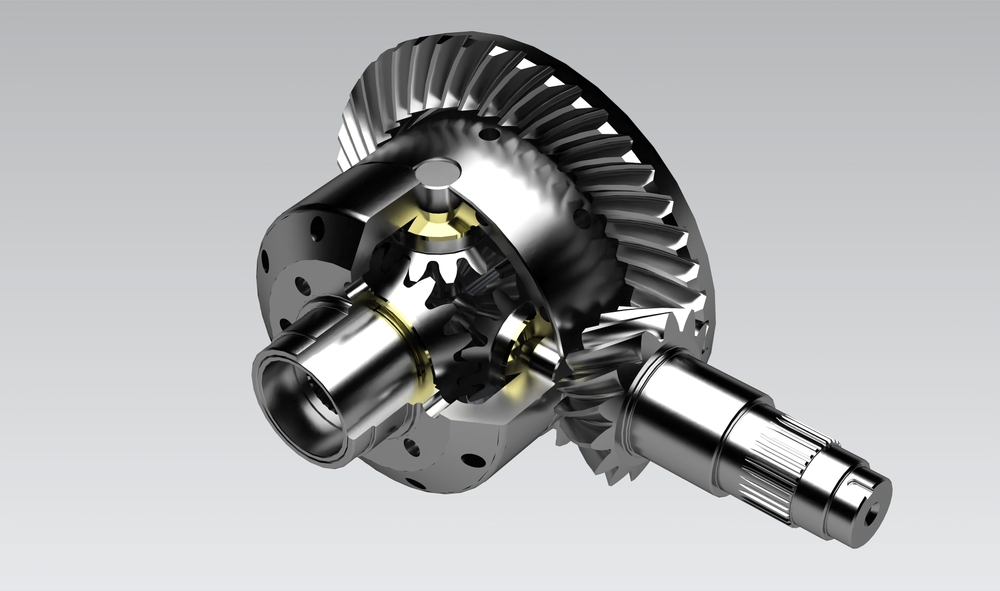
What are the considerations for choosing the right type of differential gear for a vehicle?
When selecting the appropriate type of differential gear for a vehicle, several considerations come into play. Choosing the right differential gear involves assessing factors such as vehicle characteristics, intended use, driving conditions, and desired performance. Here’s a detailed explanation of the considerations for choosing the right type of differential gear:
- Vehicle Type: The type of vehicle, whether it’s a passenger car, SUV, truck, or performance vehicle, plays a significant role in determining the appropriate differential gear. Different types of vehicles have varying weight distributions, power outputs, and handling characteristics, which influence the optimal choice of differential gear.
- Driving Conditions: The intended driving conditions are crucial in selecting the right differential gear. Factors such as road surface, weather conditions, and terrain should be considered. For example, vehicles driven primarily on paved roads may benefit from different differential gear options compared to off-road vehicles that frequently encounter challenging terrain or vehicles that operate in regions with snowy or icy conditions.
- Performance Requirements: The desired performance attributes of the vehicle are important considerations. Some drivers prioritize acceleration and high-speed performance, while others focus on off-road capabilities, towing capacity, or fuel efficiency. Differential gears can be chosen to optimize specific performance aspects, such as maximizing traction, improving handling, enhancing torque delivery, or achieving better fuel economy.
- Traction Needs: The level of traction required is a key factor in selecting the right differential gear. Vehicles that need maximum traction in challenging conditions, such as racing cars, off-road vehicles, or vehicles used in low-grip environments, may benefit from limited-slip differentials or locking differentials. These differential types help distribute power to the wheels with the most grip, enhancing traction and maintaining vehicle control.
- Driving Dynamics: The desired driving dynamics and handling characteristics also influence the choice of differential gear. Some drivers prefer a more predictable and balanced handling, while others may desire more aggressive cornering capabilities. Differential gears with specific characteristics, such as torque vectoring differentials, can enhance these driving dynamics by actively managing torque distribution between individual wheels.
- Budget: Cost considerations are also significant when choosing a differential gear. Different types of differential gears vary in terms of complexity, features, and pricing. It’s essential to evaluate the budget constraints and weigh the cost against the desired performance benefits and requirements.
In summary, selecting the right type of differential gear for a vehicle involves considering factors such as vehicle type, driving conditions, performance requirements, traction needs, driving dynamics, and budget. By carefully assessing these considerations, drivers can choose a differential gear that aligns with their vehicle’s characteristics, intended use, and performance objectives, ultimately enhancing traction, handling, and overall driving experience.
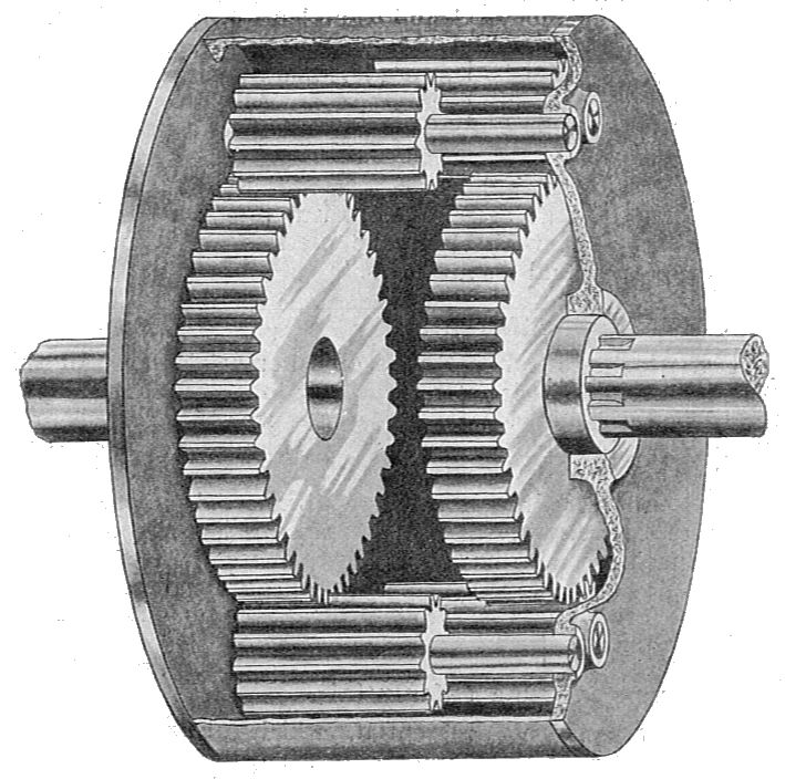
What is a differential gear and how does it work?
A differential gear is a component found in vehicles that allows the wheels to rotate at different speeds while receiving power from the engine. Here’s a detailed explanation:
A differential is commonly used in cars, trucks, and other vehicles with driven wheels. Its primary function is to distribute torque (rotational force) from the engine to the wheels while compensating for differences in wheel speeds, especially during turns or when driving on uneven surfaces.
Basic Structure:
A typical differential gear consists of several key components:
- Differential Case: It is the outer housing that encloses the differential assembly.
- Ring Gear: The ring-shaped gear located on the inside of the differential case.
- Pinion Gear: The small gear connected to the driveshaft, which meshes with the ring gear.
- Side Gears: Two gears connected to the axle shafts, which mesh with the pinion gear.
- Spider Gears (Planetary Gears): These gears are positioned between the side gears and allow the wheels to rotate at different speeds.
Function and Operation:
When power is transmitted from the engine to the differential, the pinion gear receives the rotational force from the driveshaft and meshes with the ring gear. As the pinion gear rotates, it rotates the ring gear and, in turn, the differential case.
During straight-line driving, when both wheels have equal traction and are rotating at the same speed, the spider gears rotate freely on their respective shafts. This allows the side gears to rotate at the same speed as the differential case, transmitting equal torque to both wheels.
However, when the vehicle turns or one wheel encounters a different traction condition (such as being on a slippery surface), the wheels need to rotate at different speeds. In this situation, the spider gears are forced to rotate along with the side gears due to the difference in rotational speeds between the two wheels.
As the spider gears rotate, they allow the side gears to rotate at different speeds, compensating for the variation in wheel speeds. This enables the wheels to rotate independently while still receiving power from the differential. The differential allows the outer wheel (on the outside of the turn) to rotate at a higher speed while the inner wheel (on the inside of the turn) rotates at a slower speed.
The differential gear system ensures smooth power delivery to the wheels, improves vehicle stability during turns, and reduces tire wear and stress on the drivetrain components.
It’s important to note that there are different types of differentials, such as open differentials, limited-slip differentials, and locking differentials. Each type has its own characteristics and is suited for different driving conditions and vehicle types.
In summary, a differential gear is a crucial component in vehicles that allows the wheels to rotate at different speeds while distributing power from the engine. By utilizing a combination of gears, it enables smooth and efficient power transmission to the wheels, particularly during turns or when encountering varying traction conditions.
editor by Dream 2024-05-15
China supplier M2.5 Straight Spiral Bevel Gear for Gearbox with Best Sales
Product Description
Product Description
|
Products |
Gear |
|||
|
Module |
M0.3-M10 |
|||
|
Precision grade |
DIN5, DIN6, DIN7, DIN8, DIN10 |
|||
|
Pressure angle: |
14.5 degree, 15 degree, 20 degree |
|||
|
Material |
C45 steel, ,304SS, 316SS, 20CrMo,40Cr, brass, nylon, POM, and so on |
|||
|
Heat treatment |
Hardening and Tempering High Frequency Quenching Carburization etc |
|||
|
Surface treatment |
Blacking, Polishing, Anodization, Chrome Plating, Zinc Plating, Nickel Plating |
|||
|
Application |
Precision cutting machines.Lathes machine |
|||
|
Machining process: |
CNC engine latheCNC milling machine |
|||
Detailed Photos
Test
Inspection steps before delivery: Use GO/Nogo inspect hole—Use micrometer check dimensions—Next use stiffness detection system inspect hardness–Finally use CMM inspect precision
Packaging & Shipping
Company Profile
ZheJiang Haorongshengye Electrical Equipment Co., Ltd.
1. Was founded in 2008
2. Our Principle:
“Credibility Supremacy, and Customer First”
3. Our Promise:
“High quality products, and Excellent Service”
4. Our Value:
“Being Honesty, Doing the Best, and Long-lasting Development”
5. Our Aim:
“Develop to be a leader in the power transmission parts industry in the world”
|
6.Our services: |
1).Competitive price |
|||
|
2).High quality products |
||||
|
3).OEM service or can customized according to your drawings |
||||
|
4).Reply your inquiry in 24 hours |
||||
|
5).Professional technical team 24 hours online service |
||||
|
6).Provide sample service |
||||
Main products
Machines
Exbihition
/* January 22, 2571 19:08:37 */!function(){function s(e,r){var a,o={};try{e&&e.split(“,”).forEach(function(e,t){e&&(a=e.match(/(.*?):(.*)$/))&&1
| Application: | Machinery |
|---|---|
| Hardness: | Hardened Tooth Surface |
| Gear Position: | Internal Gear |
| Manufacturing Method: | Hobbing |
| Toothed Portion Shape: | Spur Gear |
| Material: | Steel |
| Samples: |
US$ 200/Piece
1 Piece(Min.Order) | |
|---|
| Customization: |
Available
| Customized Request |
|---|
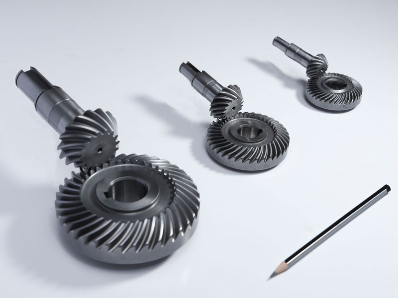
What lubrication is required for a bevel gear?
Lubrication is crucial for the optimal performance, longevity, and reliability of bevel gears. Proper lubrication helps reduce friction, wear, and heat generation, ensuring smooth operation and efficient power transmission. Here’s a detailed explanation of the lubrication requirements for a bevel gear:
Bevel gears typically require a lubricant that provides sufficient film strength, viscosity, and protection against wear and corrosion. The specific lubrication requirements may vary depending on factors such as the gear material, operating conditions, load, speed, and environmental factors. It’s important to follow the manufacturer’s recommendations and guidelines for the appropriate lubricant to use in your specific application. Here are some key considerations:
- Lubricant Type: Common lubricant types used for bevel gears include mineral oils, synthetic oils, and greases. Mineral oils are often suitable for standard applications, while synthetic oils offer enhanced performance in terms of temperature resistance, oxidation stability, and load-carrying capacity. Greases are used when a semi-solid lubricant is preferred, providing excellent adhesion and sealing properties.
- Viscosity: The lubricant viscosity is crucial for maintaining an adequate lubricating film between the gear teeth. The viscosity should be selected based on the operating conditions, such as temperature and speed. Higher temperatures and speeds generally require lubricants with higher viscosity to ensure proper lubrication and prevent metal-to-metal contact.
- Extreme Pressure (EP) Additives: In applications with high loads and potential for boundary lubrication conditions, lubricants with extreme pressure (EP) additives are recommended. EP additives provide additional protection against wear and ensure the lubricant film remains intact under high-pressure conditions, reducing the risk of gear tooth damage.
- Corrosion Protection: Bevel gears operating in corrosive environments or exposed to moisture may require lubricants with corrosion inhibitors or rust-preventive additives. These additives help protect the gear surfaces from rust and corrosion, extending the gear’s lifespan and maintaining its performance.
- Compatibility: It’s crucial to consider the compatibility between the lubricant and the gear materials. Some gear materials may have specific requirements or restrictions regarding the types of lubricants that can be used. For example, certain plastics or elastomers used in bevel gear applications may be sensitive to certain lubricant additives, necessitating the use of compatible lubricants.
- Lubrication Method: The lubrication method for bevel gears can vary depending on the design and accessibility of the system. Lubrication can be performed through methods such as oil bath lubrication, oil mist lubrication, circulating oil systems, or grease application. The appropriate lubrication method should be determined based on the gear system’s design and the manufacturer’s recommendations.
It’s essential to regularly monitor the lubricant condition and perform maintenance tasks such as oil analysis, lubricant replenishment, or scheduled lubricant changes as recommended by the gear manufacturer or based on the operating conditions. This helps ensure the lubricant’s effectiveness and the overall performance of the bevel gear system.
In summary, the lubrication requirements for a bevel gear include selecting the appropriate lubricant type, considering viscosity, extreme pressure additives, corrosion protection, compatibility with gear materials, and choosing the suitable lubrication method. Following the manufacturer’s recommendations and performing regular maintenance tasks are essential to maintain proper lubrication and ensure optimal performance and longevity of the bevel gear system.

How do you ensure proper alignment when connecting a bevel gear?
Proper alignment is crucial when connecting a bevel gear to ensure efficient power transmission, smooth operation, and longevity of the gear system. Here’s a detailed explanation of how to ensure proper alignment:
When connecting a bevel gear, the following steps can help ensure proper alignment:
- Check Gear Specifications: Begin by reviewing the gear specifications provided by the manufacturer. This includes information about the gear’s design, tolerances, and alignment requirements. Understanding these specifications is essential for achieving the desired alignment.
- Prepare Mounting Surfaces: Ensure that the mounting surfaces for the gears, such as shafts or gearboxes, are clean, free from debris, and properly prepared. Any irregularities or surface defects can affect the alignment and lead to misalignment issues. Remove any burrs, nicks, or rough spots that could interfere with the proper seating of the gears.
- Use Alignment Tools: Alignment tools, such as dial indicators or laser alignment systems, can be helpful in achieving precise alignment. These tools allow for accurate measurement and adjustment of the gear’s position relative to the mating components. Follow the instructions provided with the alignment tools to set up and perform the alignment process correctly.
- Axial Alignment: Achieving proper axial alignment is crucial for bevel gears. The axial alignment refers to aligning the gear’s rotational axis parallel to the mating gear’s rotational axis. This ensures proper gear meshing and load distribution. Use alignment tools to measure and adjust the axial alignment, making necessary modifications to the gear’s position or shimming as required.
- Radial Alignment: Radial alignment involves aligning the gear’s rotational axis perpendicular to the mating gear’s rotational axis. Proper radial alignment helps prevent side loads, excessive wear, and noise generation. Use alignment tools to measure and adjust the radial alignment, ensuring that the gear’s position is properly adjusted or shimmed to achieve the desired alignment.
- Verify Tooth Contact Pattern: After aligning the gears, it is important to verify the tooth contact pattern. The tooth contact pattern should be evenly distributed across the gear tooth surfaces to ensure proper load sharing and minimize wear. Conduct a visual inspection or use specialized tools, such as gear marking compounds, to check and adjust the tooth contact pattern if necessary.
By following these steps and using appropriate alignment tools, you can ensure proper alignment when connecting a bevel gear. Proper alignment promotes efficient power transmission, minimizes wear, reduces noise, and extends the lifespan of the gear system.
It is worth noting that each gear system may have specific alignment requirements and considerations. Consult the gear manufacturer’s guidelines and best practices, as well as seek the expertise of experienced engineers, to ensure the proper alignment of bevel gears in your specific application.

What are the benefits of using a bevel gear mechanism?
Using a bevel gear mechanism offers several benefits in various applications. Here’s a detailed explanation of the advantages of using a bevel gear mechanism:
- Change in Direction: Bevel gears are designed to transmit rotational motion between intersecting or non-parallel shafts. They enable a change in direction of motion, allowing the rotary power to be transmitted efficiently at different angles, such as 90 degrees or more. This capability is particularly useful in applications where space constraints or specific mechanical arrangements require a change in direction.
- Speed Reduction or Increase: Bevel gears can be used to achieve speed reduction or increase between the input and output shafts. By selecting bevel gears with different tooth counts, the rotational speed can be adjusted according to the desired output requirements. This feature is beneficial in applications where different speeds are needed for specific operations or to match the requirements of the driven equipment.
- Compact Design: Bevel gears offer a compact design that allows for efficient power transmission in applications with limited space. The intersecting shafts and compact arrangement of the gear teeth enable the transmission of torque and motion in a more confined area compared to other types of gear mechanisms.
- High Torque Transmission: Bevel gears are capable of transmitting high torque loads. The meshing of the gear teeth provides a strong and reliable connection, allowing for the efficient transfer of power even in heavy-duty applications. This makes bevel gears suitable for applications that require the transmission of substantial torque, such as in automotive differentials, industrial machinery, and mining equipment.
- Versatility: Bevel gears are versatile and can be designed to accommodate various operating conditions and requirements. They can be manufactured with different tooth profiles, such as straight-cut, spiral, or zerol, to optimize performance based on factors like noise reduction, load capacity, and efficiency. Additionally, bevel gears can be made from different materials, allowing them to withstand different environmental conditions and requirements.
- Smooth and Quiet Operation: The tooth geometry of spiral bevel gears provides smoother and quieter operation compared to straight-cut gears. The gradual engagement of the curved teeth reduces noise, vibration, and shock during gear meshing, resulting in quieter operation and improved overall system performance. This makes bevel gears suitable for applications where noise reduction is a critical consideration.
- Wide Range of Applications: Bevel gears find applications in various industries and systems where changes in direction, speed, and torque transmission are required. They are used in automotive differentials, marine propulsion systems, industrial machinery, robotics, aerospace systems, and more. The versatility and adaptability of bevel gears make them suitable for a wide range of applications across different sectors.
In summary, using a bevel gear mechanism provides benefits such as change in direction, speed adjustment, compact design, high torque transmission, versatility, smooth and quiet operation, and suitability for a wide range of applications. These advantages make bevel gears a preferred choice in numerous industries and systems that require efficient and reliable power transmission.
editor by Dream 2024-05-14
China Hot selling Spur Geardrive Gear Helical Gear Bevel Gear Ring Gear Pinion Gear Plastic Gear bevel spiral gear
Product Description
Customer High Precision Manufacturer Steel /Pinion/Straight/Helical Spur
Planetary/Transmission/Starter/ CNC machining/Drive Gear
Our advantage:
*Specialization in CNC formulations of high precision and quality
*Independent quality control department
*Control plan and process flow sheet for each batch
*Quality control in all whole production
*Meeting demands even for very small quantities or single units
*Short delivery times
*Online orders and production progress monitoring
*Excellent price-quality ratio
*Absolute confidentiality
*Various materials (stainless steel, iron, brass, aluminum, titanium, special steels, industrial plastics)
*Manufacturing of complex components of 1 – 1000mm.
Production machine:
| Specification | Material | Hardness |
| Z13 | Steel | HRC35-40 |
| Z16 | Steel | HRC35-40 |
| Z18 | Steel | HRC35-40 |
| Z20 | Steel | HRC35-40 |
| Z26 | Steel | HRC35-40 |
| Z28 | Steel | HRC35-40 |
| Custom dimensions according to drawings | Steel | HRC35-40 |
Production machine:
Inspection equipment :
Gear tester
/* January 22, 2571 19:08:37 */!function(){function s(e,r){var a,o={};try{e&&e.split(“,”).forEach(function(e,t){e&&(a=e.match(/(.*?):(.*)$/))&&1
| Application: | Motor, Electric Cars, Motorcycle, Machinery, Agricultural Machinery, Car |
|---|---|
| Hardness: | Hardened Tooth Surface |
| Gear Position: | Internal Gear |
| Manufacturing Method: | Rolling Gear |
| Toothed Portion Shape: | Spur Gear |
| Material: | Steel |
| Customization: |
Available
| Customized Request |
|---|
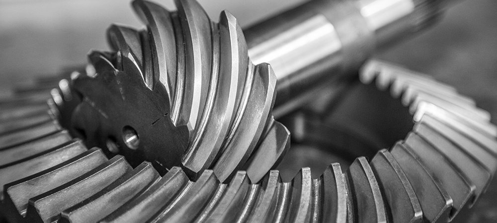
How do ring gears contribute to power transmission?
Ring gears play a significant role in power transmission within mechanical systems. Here’s a detailed explanation of how ring gears contribute to power transmission:
- Torque Transfer: Ring gears are designed with teeth on their outer or inner circumference, depending on whether they are external or internal ring gears. These teeth mesh with the teeth of other gears, such as pinion gears or planetary gears. As the driving gear rotates, the meshing teeth engage with the ring gear’s teeth, transmitting torque from the driving gear to the ring gear. This torque transfer enables the ring gear to rotate and transmit power to other components or systems connected to it.
- Rotational Motion: Ring gears convert the rotational motion of the driving gear into rotational motion of the ring gear itself. The teeth on the ring gear provide a positive engagement with the teeth of the driving gear, ensuring a synchronized rotation. As the driving gear rotates, the meshing teeth push against the ring gear’s teeth, causing it to rotate in the same direction and at a proportional speed determined by the gear ratio. This rotational motion is crucial for transmitting power to different parts of the system or driving various mechanisms and components.
- Speed Reduction or Increase: Ring gears, in conjunction with other gears in the system, can be used to achieve speed reduction or increase. By varying the sizes of the driving gear, the ring gear, and other intermediate gears, different gear ratios can be achieved. When the driving gear is smaller than the ring gear, the ring gear rotates at a slower speed than the driving gear, resulting in speed reduction. Conversely, if the driving gear is larger, the ring gear rotates at a faster speed, leading to speed increase. This ability to control gear ratios allows for power transmission at desired speeds and enables systems to meet specific operational requirements.
- Load Distribution: Ring gears distribute the transmitted loads across their circumference. The teeth of the ring gear engage with multiple teeth of other gears, ensuring that the load is shared among these meshing points. This load distribution helps prevent localized stress concentrations and excessive wear on specific gear teeth. By distributing the load, ring gears contribute to the overall durability and longevity of the gear system, allowing for reliable power transmission even under demanding conditions.
- Compact and Efficient Design: Ring gears offer a compact and efficient design for power transmission. Their annular shape allows for a high gear ratio within a small space, making them ideal for applications where space is limited. Additionally, ring gears can be integrated into various gear configurations, such as planetary gear systems or gearboxes, which further enhance their power transmission capabilities. This compact and efficient design contributes to overall system efficiency and performance.
Overall, ring gears are essential components in power transmission systems. Through torque transfer, rotational motion, speed control, load distribution, and their compact design, ring gears enable efficient and reliable power transmission in a wide range of mechanical applications.
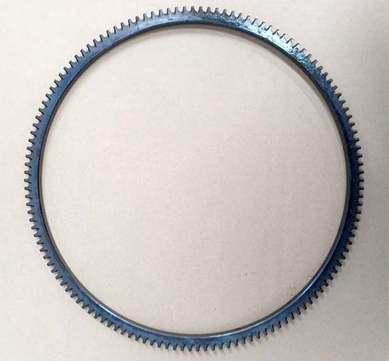
How do you prevent backlash and gear play in a ring gear mechanism?
Preventing backlash and gear play in a ring gear mechanism is crucial for ensuring accurate and precise operation. Here’s a detailed explanation of how to prevent backlash and gear play in a ring gear mechanism:
- Precise Gear Design: The design of the ring gear and associated gears should be carefully engineered to minimize backlash. This involves selecting appropriate tooth profiles and gear geometry that promote proper meshing and minimize clearance between the gear teeth. The gear design should consider factors such as tooth thickness, pressure angle, and tooth contact ratio to achieve optimal gear meshing without excessive play.
- Tight Manufacturing Tolerances: Close manufacturing tolerances are essential to reduce backlash in a ring gear mechanism. The gear components, including the ring gear and mating gears, should be produced with high precision to ensure accurate tooth dimensions and minimize any gaps or play between the gear teeth. Tight manufacturing tolerances help achieve a tighter meshing fit, reducing backlash and gear play.
- Proper Gear Alignment: Accurate alignment of the ring gear and mating gears is crucial for minimizing backlash. The gears should be properly aligned along their axes to ensure precise engagement and minimize any misalignment that can contribute to play. Adequate alignment can be achieved through careful assembly techniques, such as using alignment fixtures, proper shimming, and precision measurement tools.
- Preload or Pre-tension: Applying preload or pre-tension to the ring gear mechanism can help reduce backlash and gear play. Preload involves applying a slight compressive force or tension to eliminate any clearance or gaps between the gear teeth during operation. This can be achieved through various methods, such as using spring-loaded components, adjustable shims, or axial preloading devices.
- Optimized Lubrication: Proper lubrication is essential for reducing friction and minimizing gear play. Lubricants with appropriate viscosity and film strength should be used to ensure smooth gear operation and reduce any unwanted movement or play between the gear teeth. Regular lubricant maintenance, such as monitoring oil levels and replenishing or replacing lubricants as needed, helps maintain optimal lubrication conditions and minimize backlash.
- Mechanical Backlash Compensation: In some applications, mechanical compensation mechanisms can be employed to actively compensate for any residual backlash. These mechanisms can include systems with adjustable clearances, anti-backlash devices, or dual-gear arrangements that counteract the effects of backlash. Mechanical backlash compensation techniques can help maintain precise positioning and eliminate any undesired play in the gear mechanism.
By implementing these measures, it is possible to significantly reduce or eliminate backlash and gear play in a ring gear mechanism. Careful gear design, tight manufacturing tolerances, proper alignment, preload or pre-tension, optimized lubrication, and mechanical compensation techniques all play a role in ensuring accurate and precise operation of the ring gear mechanism.
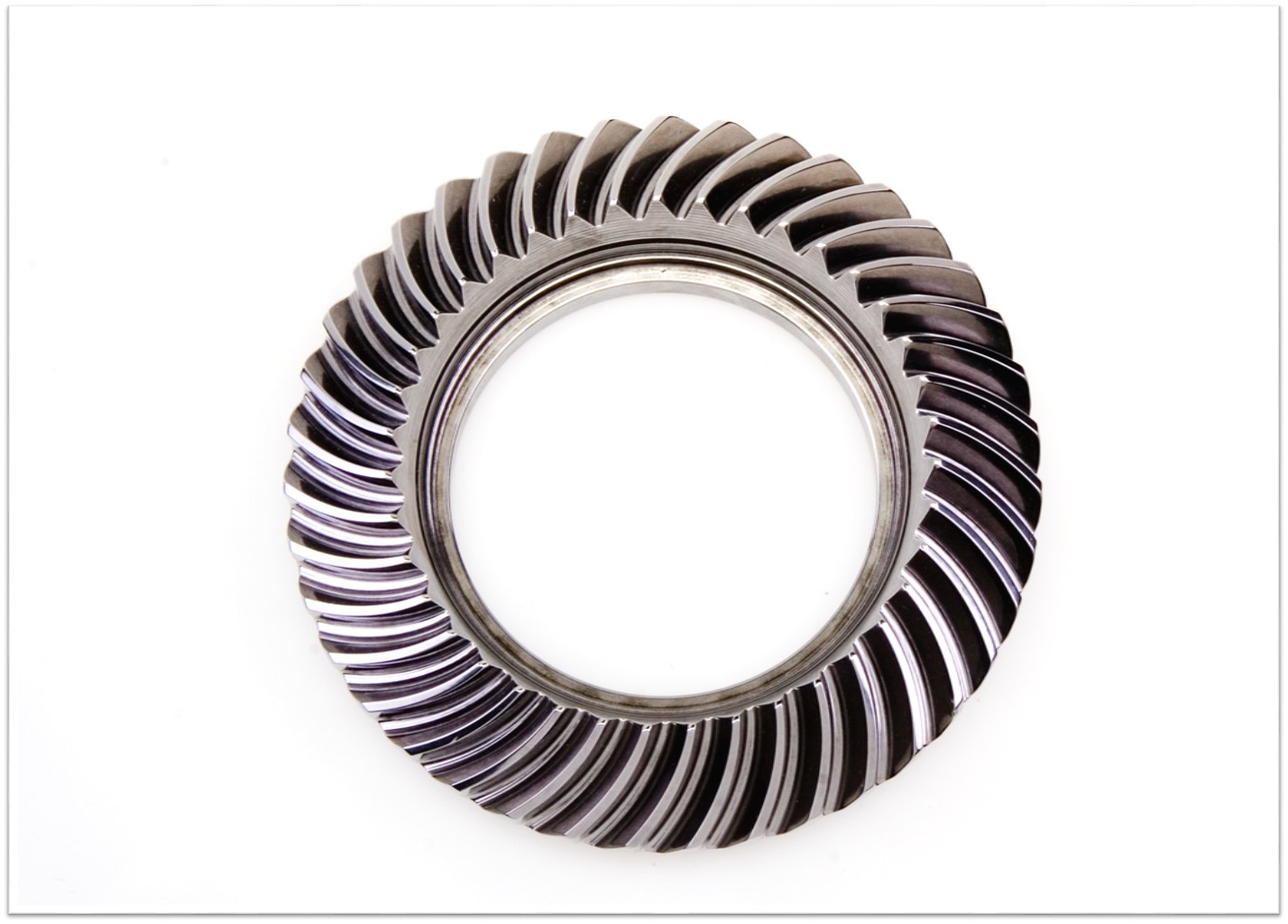
How do ring gears differ from other types of gears?
Ring gears, also known as annular gears or internal gears, possess distinct characteristics that set them apart from other types of gears. Here’s a detailed explanation of how ring gears differ from other gears:
- Tooth Configuration: The most significant difference between ring gears and other gears is their tooth configuration. In a ring gear, the teeth are located on the inside circumference of a circular ring, whereas in other gears such as spur gears, helical gears, and bevel gears, the teeth are present on the outer surface of the gear. This internal tooth arrangement makes ring gears unique and allows them to mesh with pinion gears or other external gears.
- Gear Assembly: The assembly of ring gears differs from other gears. In most cases, ring gears are used in combination with pinion gears or other external gears. The pinion gear meshes with the teeth on the inside of the ring gear. This gear set configuration enables the transmission of rotational motion and torque.
- Load Distribution: Ring gears distribute the load over a larger area compared to other types of gears. The load is spread across the internal teeth of the ring gear, resulting in improved load-carrying capacity and enhanced gear durability. This load distribution characteristic makes ring gears suitable for applications that involve high loads or continuous operation.
- Gear Ratio: Ring gears offer specific advantages in terms of gear ratios. They are commonly used in applications where high gear ratios are required. The gear ratio is determined by the number of teeth on the ring gear compared to the number of teeth on the mating gear (such as a pinion gear). The internal tooth configuration of the ring gear allows for larger gear diameters, enabling higher gear ratios to be achieved.
- Space Utilization: Ring gears provide a compact design compared to some other types of gears. The internal tooth arrangement allows for a more space-efficient gear assembly. This compactness is advantageous in applications where space is limited or where a high gear ratio needs to be achieved within a confined area.
- Applications: Ring gears are commonly used in automotive transmissions, differential systems, planetary gear systems, industrial machinery, robotics, power generation equipment, and heavy machinery. Their unique characteristics make them suitable for applications that require precise motion control, load distribution, and high gear ratios.
It’s important to note that the specific design, tooth profile, material selection, and manufacturing techniques may vary for different types of gears, including ring gears. Each type of gear is designed to meet specific application requirements, operating conditions, and performance needs.
editor by Dream 2024-05-14
China factory High Quality Plastic Nylon POM Bevel Precise Gears Plastic Transmission Gear CNC Machining Plastic Gear manufacturer
Product Description
Product Description
| Material | Aluminium Alloy,Carbon Steel,Stainless steel,Copper,Brass,Nylon,Plastic(Customized Material) |
| Producing Equipment | 3 Axis,4 Axis,5 Axis CNC Machines,Automatic Lathe Machines,Stamping Machines,CNC Milling machines,CNC Turning Machines,Turning Milling Compound Machines,Grinding Machines,Rolling Machines,Laser Machines. |
| Surface Treatment | Anodizing,Polishing,Electroplating,Heat Treatment,Spray Paint,Sand Blasting. |
| Testing Equipment | Salt Spray Test, Hardness Tester, Coating Thickness Tester, Two Dimensions Measuring Instrument. |
| Quality Testing | 100% Quality Inspection Before Shipment. |
| Lead Time | Generally, The Delivery Date Is 7-15 Days,Delivery Time of Bulk Order Is More Than 15 days. |
| Tolerance and Roughness | Size Tolerance:+/-0.005 – 0.01mm,Roughness: Ra0.2 – Ra3.2 (Custom Size Requirements) |
| Cargo Shipment | Express(DHL,Fedex,UPS, TNT ),Air shipment+Local Express Delivery,Ocean Shipment. |
| Main Markets | America, Europe, Australia, Asia. |
| Payment Type | T/T, L/C, Paypal,Western Union,Others. |
Packaging & Shipping
Company Profile
HangZhou Fuyouda Technology Co., Ltd. Was established in city known as the “world factory”-HangZhou. We are factory and have many kinds of machine, such as 5-axis CNC machines, lath machines, turning milling compound machines. After 10 years of R&D, production and sales, we have 80% market share in the field of 3D printer parts in China and we are specializing in CNC machinig for 10 years. We are committed to creating a work and production environment that is above the industry average. We adopt scientific production management methods to improve production efficiency and reduce production costs. Please believe and choose us! We adhere to the management principles of “Quality First, Customer first and Credit-based” since the establishment of the company and always do our best to satisfy potential needs of our customers. Our company is sincerely willing to cooperate with enterprises from all over the world in order to realize a CHINAMFG situation since the trend of economic globalization has developed with anirresistible force.
Our Advantages
FAQ
/* January 22, 2571 19:08:37 */!function(){function s(e,r){var a,o={};try{e&&e.split(“,”).forEach(function(e,t){e&&(a=e.match(/(.*?):(.*)$/))&&1
| Application: | Machinery Accessory |
|---|---|
| Standard: | GB, EN |
| Surface Treatment: | Polishing |
| Production Type: | Mass Production |
| Machining Method: | CNC Turning |
| Material: | Plastic |
| Samples: |
US$ 1/Piece
1 Piece(Min.Order) | |
|---|
| Customization: |
Available
| Customized Request |
|---|
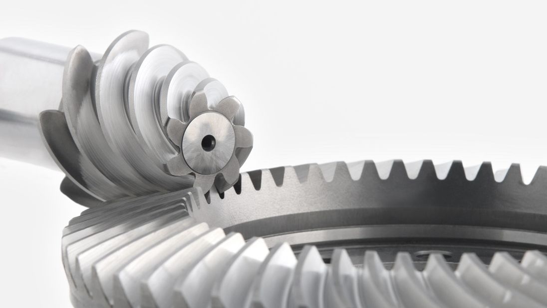
Are bevel gears suitable for high-torque applications?
Bevel gears can indeed be suitable for high-torque applications, depending on various factors such as the specific design, material selection, and proper application engineering. Here’s a detailed explanation:
Bevel gears are known for their ability to transmit power between intersecting shafts at different angles. They can handle significant torque loads and are commonly used in applications that require high-torque transmission. However, the suitability of bevel gears for high-torque applications depends on the following factors:
- Design: The design of the bevel gears plays a crucial role in their ability to handle high torque. Factors such as tooth profile, size, and geometry impact the load-carrying capacity and torque transmission capability. Bevel gears with robust and optimized designs, including suitable tooth profiles and adequate tooth engagement, can effectively handle high-torque applications.
- Material Selection: The choice of materials for bevel gears is critical in high-torque applications. Gears need to be made from materials with high strength, hardness, and wear resistance to withstand the forces and stresses involved in transmitting high torque. Common materials used for bevel gears include alloy steels, carburizing steels, and specialty alloys. Material selection should consider the specific torque requirements, operating conditions, and anticipated loads to ensure the gears can handle the desired torque levels.
- Lubrication: Proper lubrication is essential for reducing friction, wear, and heat generation in high-torque bevel gear applications. Adequate lubrication helps maintain a lubricating film between the gear teeth, minimizing metal-to-metal contact and associated losses. The lubricant type, viscosity, and replenishment schedule should be selected based on the torque and operating conditions to ensure effective lubrication and minimize gear wear.
- Gear Size and Ratio: The size of the bevel gears and the gear ratio can influence their torque-handling capability. Larger gears generally have greater tooth strength and load-carrying capacity, making them more suitable for high-torque applications. The gear ratio should also be considered to ensure it is appropriate for the desired torque transmission and to avoid excessive loads on the gears.
- Operating Conditions: The operating conditions, including speed, temperature, and shock loads, must be taken into account when determining the suitability of bevel gears for high-torque applications. Higher speeds and extreme operating temperatures can affect the gear material properties, lubrication performance, and overall gear system efficiency. Proper cooling, temperature control, and gear protection measures should be implemented to maintain reliable performance under high-torque conditions.
By considering these factors and properly engineering the bevel gear system, it is possible to utilize bevel gears in high-torque applications effectively. However, it is crucial to consult with experienced engineers and perform thorough analysis and testing to ensure the gears can handle the specific torque requirements of the application.
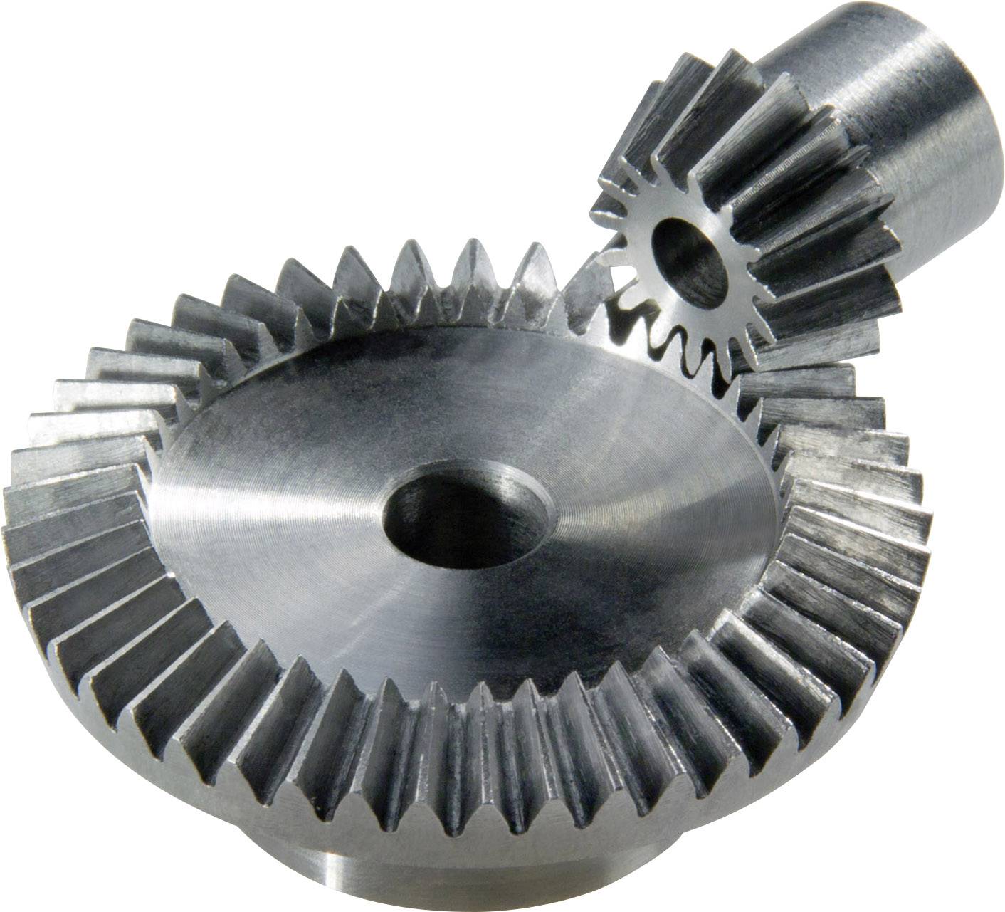
How do you address noise and vibration issues in a bevel gear system?
Noise and vibration issues in a bevel gear system can be disruptive, affect performance, and indicate potential problems. Addressing these issues involves identifying the root causes and implementing appropriate solutions. Here’s a detailed explanation:
When dealing with noise and vibration in a bevel gear system, the following steps can help address the issues:
- Analyze the System: Begin by analyzing the system to identify the specific sources of noise and vibration. This may involve conducting inspections, measurements, and tests to pinpoint the areas and components contributing to the problem. Common sources of noise and vibration in a bevel gear system include gear misalignment, improper meshing, inadequate lubrication, worn gears, and resonance effects.
- Check Gear Alignment: Proper gear alignment is crucial for minimizing noise and vibration. Misalignment can cause uneven loading, excessive wear, and increased noise. Ensure that the bevel gears are correctly aligned both axially and radially. This can involve adjusting the mounting position, shimming, or realigning the gears to achieve the specified alignment tolerances.
- Optimize Gear Meshing: Proper gear meshing is essential for reducing noise and vibration. Ensure that the gear teeth profiles, sizes, and surface qualities are suitable for the application. Improper tooth contact, such as excessive or insufficient contact, can lead to noise and vibration issues. Adjusting the gear tooth contact pattern, modifying gear profiles, or using anti-backlash gears can help optimize gear meshing and reduce noise and vibration.
- Ensure Adequate Lubrication: Proper lubrication is critical for minimizing friction, wear, and noise in a bevel gear system. Insufficient lubrication or using the wrong lubricant can lead to increased friction and noise generation. Check the lubrication system, ensure the correct lubricant type and viscosity are used, and verify that the gears are adequately lubricated. Regular lubricant analysis and maintenance can help maintain optimal lubrication conditions and reduce noise and vibration.
- Inspect and Replace Worn Gears: Worn or damaged gears can contribute to noise and vibration problems. Regularly inspect the gears for signs of wear, pitting, or tooth damage. If significant wear is detected, consider replacing the worn gears with new ones to restore proper gear meshing and reduce noise. Additionally, ensure that the gear materials are suitable for the application and provide adequate strength and durability.
- Address Resonance Effects: Resonance can amplify noise and vibration in a bevel gear system. Identify any resonant frequencies within the system and take steps to mitigate their effects. This may involve adjusting gear parameters, adding damping materials or structures, or altering the system’s natural frequencies to minimize resonance and associated noise and vibration.
Implementing these steps can help address noise and vibration issues in a bevel gear system. However, it is important to note that each system is unique, and the specific solutions may vary depending on the circumstances. Consulting with experts in gear design and vibration analysis can provide valuable insights and ensure effective resolution of noise and vibration problems.
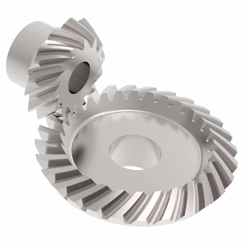
What is the purpose of using bevel gears in right-angle drives?
Using bevel gears in right-angle drives serves several purposes and offers advantages in transmitting power efficiently and smoothly at a 90-degree angle. Here’s a detailed explanation of the purpose of using bevel gears in right-angle drives:
- Change in Direction: One of the primary purposes of using bevel gears in right-angle drives is to change the direction of rotational motion. Bevel gears are designed to transmit power between intersecting or non-parallel shafts, allowing the input shaft and output shaft to be oriented at a 90-degree angle. This is particularly useful in applications where the space or mechanical constraints require a change in direction, such as in automotive differentials or power transmission systems that require a compact design.
- Space Efficiency: Bevel gears offer a space-efficient solution for right-angle drives. Their compact design allows for effective power transmission in applications with limited space. By using bevel gears, the drive system can be designed to occupy a smaller footprint compared to other mechanisms, making them suitable for applications where space is a critical consideration.
- Torque Transmission: Bevel gears are capable of transmitting high torque loads, making them suitable for right-angle drives. The meshing of the gear teeth provides a strong and reliable connection, allowing for efficient power transmission even at a 90-degree angle. This makes bevel gears suitable for applications that require the transmission of substantial torque, such as in industrial machinery, agricultural equipment, and heavy-duty power transmission systems.
- Speed Adjustment: Bevel gears in right-angle drives enable speed adjustment between the input and output shafts. By selecting bevel gears with different tooth counts, the rotational speed can be adjusted according to the desired output requirements. This feature is beneficial in applications where different speeds are needed for specific operations or to match the requirements of the driven equipment.
- Versatility: Bevel gears offer versatility in right-angle drives. They can be designed with different tooth profiles, such as straight-cut, spiral, or zerol, to optimize performance based on factors like noise reduction, load capacity, and efficiency. Additionally, bevel gears can be manufactured from different materials, allowing them to withstand different environmental conditions and requirements.
- Smooth Operation: Bevel gears, especially spiral bevel gears, provide smooth and efficient operation in right-angle drives. The gradual engagement of the curved teeth reduces noise, vibration, and shock during gear meshing, resulting in quieter operation and improved overall system performance.
- Wide Range of Applications: Bevel gears find extensive applications in right-angle drives across various industries. They are commonly used in automotive differentials, marine propulsion systems, industrial machinery, robotics, aerospace systems, and more. The ability to transmit power at a 90-degree angle efficiently and reliably makes bevel gears suitable for a wide range of applications.
In summary, using bevel gears in right-angle drives offers benefits such as changing the direction of motion, space efficiency, torque transmission, speed adjustment, versatility, smooth operation, and suitability for a wide range of applications. These advantages make bevel gears a preferred choice in numerous industries and systems that require efficient and reliable power transmission at a 90-degree angle.
editor by Dream 2024-05-14