Product Description
CHINAMFG TEC Product Description :
| Material | Carbon Steel | SAE1571, SAE1045, Cr12, 40Cr, Y15Pb, 1214Letc | |
| Alloy Steel | 20CrMnTi, 16MnCr5, 20CrMnMo, 41CrMo, 17CrNiMo5etc | ||
| Brass/Bronze | HPb59-1, H70, CuZn39Pb2, CuZn40Pb2, C38000, CuZn40etc | ||
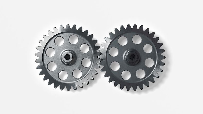
| Type | OEM ODM High precision Bevel Gear for car ,farm,industry | ||
| Treatment | Heat treatments, Carburizing, Polishing | ||
| Standard | ISO /R 606 | ||
| Machining process | fabrication,stamping,deep drawing,gear hobbing, gear milling, gear shaping, machining and assembly gear broaching, gear grinding and gear gaping | ||
| Module | 1.0, 1.25, 1.5, 1.75, 2.0, 2.25, 2.5….8.0 etc | ||
| Tolerance control | Outer Diameter:±0.005mm | Length Dimension:±0.05 mm | |
| Teeth accuracy | GB1244-85, DIN8188, ISO/R 606 , ANSI B 29.1M | ||
| Heat treatment | Quenching & Tempering, Carburizing & Quenching, High-frequency Hardening, Carbonitriding… | ||
| Surface treatment | Blacking, Polishing, Anodization, Chrome plating, Zinc plating, Nickel plating… | ||
Advantages:
1. Professional gears manufacturer
2.Experienced in Cooperate with big Companies
3. Professional gears Engineering Capability
4.Stable gears Quality
5.Reasonable gears Prices
6.Small gears Orders Accepted
7.Continuous gears quality improvements
8. High gears quality Performance
9.Short gears lead time and shipment
10.Professional gears service
We can provide with sample for quality and function testing.
/* January 22, 2571 19:08:37 */!function(){function s(e,r){var a,o={};try{e&&e.split(“,”).forEach(function(e,t){e&&(a=e.match(/(.*?):(.*)$/))&&1
| Casting Method: | Sand Casting |
|---|---|
| Casting Form Material: | Sand |
| Casting Metal: | Cast Iron |
| Casting Form Usage Count: | Disposable |
| Surface Treatment: | Spray-Paint |
| Coating: | Painting |
| Samples: |
US$ 5/Piece
1 Piece(Min.Order) | |
|---|
| Customization: |
Available
| Customized Request |
|---|
How do you calculate the efficiency of a spur gear?
Calculating the efficiency of a spur gear involves considering the power losses that occur during gear operation. Here’s a detailed explanation:
In a gear system, power is transmitted from the driving gear (input) to the driven gear (output). However, due to various factors such as friction, misalignment, and deformation, some power is lost as heat and other forms of energy. The efficiency of a spur gear represents the ratio of the output power to the input power, taking into account these power losses.
Formula for Calculating Gear Efficiency:
The efficiency (η) of a spur gear can be calculated using the following formula:
η = (Output Power / Input Power) × 100%
Where:
η is the efficiency of the gear system expressed as a percentage.
Output Power is the power delivered by the driven gear (output) in the gear system.
Input Power is the power supplied to the driving gear (input) in the gear system.
Factors Affecting Gear Efficiency:
The efficiency of a spur gear is influenced by several factors, including:
- Tooth Profile: The tooth profile of the gear affects the efficiency. Well-designed gear teeth with accurate involute profiles can minimize friction and power losses during meshing.
- Lubrication: Proper lubrication between the gear teeth reduces friction, wear, and heat generation, improving gear efficiency. Insufficient or inadequate lubrication can result in increased power losses and reduced efficiency.
- Gear Material: The selection of gear material affects efficiency. Materials with low friction coefficients and good wear resistance can help minimize power losses. Higher-quality materials and specialized gear coatings can improve efficiency.
- Gear Alignment and Meshing: Proper alignment and precise meshing of the gear teeth are essential for optimal efficiency. Misalignment or incorrect gear meshing can lead to increased friction, noise, and power losses.
- Bearing Friction: The efficiency of a gear system is influenced by the friction in the bearings supporting the gear shafts. High-quality bearings with low friction characteristics can contribute to improved gear efficiency.
- Load Distribution: Uneven load distribution across the gear teeth can result in localized power losses and reduced efficiency. Proper design and gear system configuration should ensure even load distribution.
Interpreting Gear Efficiency:
The calculated gear efficiency indicates the percentage of input power that is effectively transmitted to the output. For example, if a gear system has an efficiency of 90%, it means that 90% of the input power is converted into useful output power, while the remaining 10% is lost as various forms of power dissipation.
It’s important to note that gear efficiency is not constant and can vary with operating conditions, lubrication quality, gear wear, and other factors. The calculated efficiency serves as an estimate and can be influenced by specific system characteristics and design choices.
By considering the factors affecting gear efficiency and implementing proper design, lubrication, and maintenance practices, gear efficiency can be optimized to enhance overall gear system performance and minimize power losses.
How do you install a spur gear system?
Installing a spur gear system involves several steps to ensure proper alignment, engagement, and operation. Here’s a detailed explanation of how to install a spur gear system:
- Preparation: Before installation, gather all the necessary components, including the spur gears, shafts, bearings, and any additional mounting hardware. Ensure that the gear system components are clean and free from debris or damage.
- Shaft Alignment: Proper shaft alignment is crucial for the smooth operation of a spur gear system. Ensure that the shafts on which the gears will be mounted are aligned accurately and parallel to each other. This can be achieved using alignment tools such as dial indicators or laser alignment systems. Adjust the shaft positions as needed to achieve the desired alignment.
- Positioning the Gears: Place the spur gears on the respective shafts in the desired configuration. Ensure that the gears are positioned securely and centered on the shafts. For shafts with keyways, align the gears with the key and ensure a proper fit. Use any necessary mounting hardware, such as set screws or retaining rings, to secure the gears in place.
- Checking Gear Engagement: Verify that the teeth of the gears mesh properly with each other. The gear teeth should align accurately and smoothly without any excessive gaps or interference. Rotate the gears by hand to ensure smooth and consistent meshing throughout their rotation. If any misalignment or interference is observed, adjust the gear positions or shaft alignment accordingly.
- Bearing Installation: If the spur gear system requires bearings to support the shafts, install the bearings onto the shafts. Ensure that the bearings are the correct size and type for the application. Press or slide the bearings onto the shafts until they are seated securely against any shoulder or bearing housing. Use appropriate methods and tools to prevent damage to the bearings during installation.
- Lubrication: Apply a suitable lubricant to the gear teeth and bearings to ensure smooth operation and reduce friction. Refer to the gear manufacturer’s recommendations for the appropriate lubrication type and amount. Proper lubrication helps minimize wear, noise, and heat generation in the gear system.
- Final Inspection: Once the gears, shafts, and bearings are installed, perform a final inspection of the entire spur gear system. Check for any unusual noises, misalignment, or binding during manual rotation. Verify that the gears are securely mounted, shafts are properly aligned, and all fasteners are tightened to the specified torque values.
It’s important to follow the specific installation instructions provided by the gear manufacturer to ensure proper installation and operation. Additionally, consult any applicable industry standards and guidelines for gear system installation.
By carefully following these installation steps, you can ensure a well-aligned and properly functioning spur gear system in your machinery or equipment.
Can you explain the concept of straight-cut teeth in spur gears?
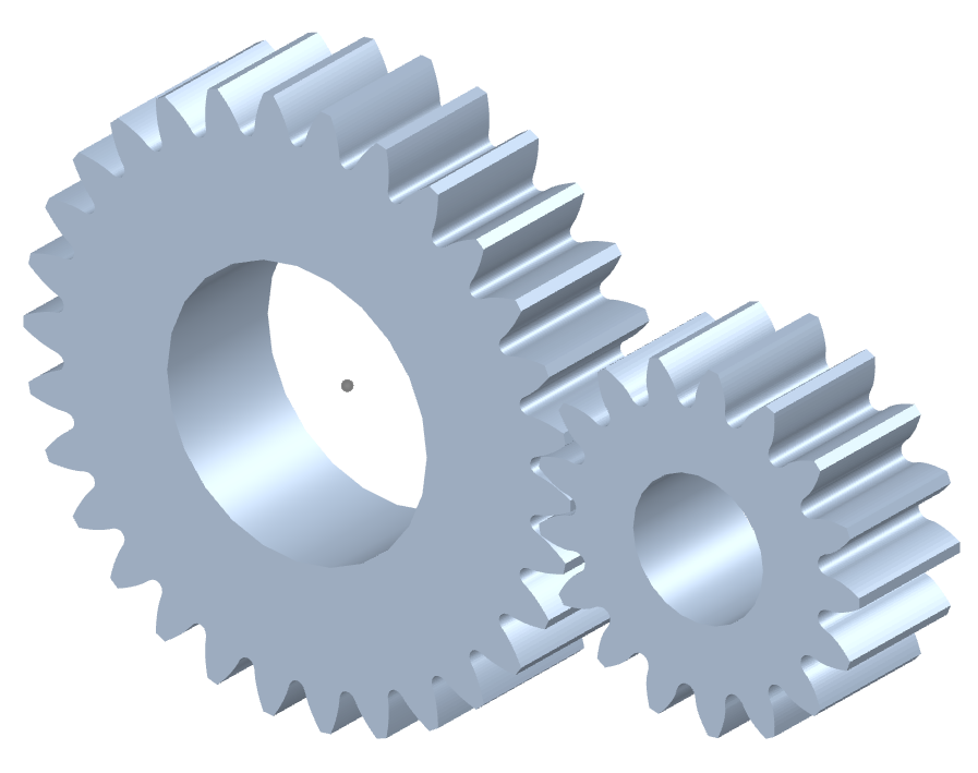
The concept of straight-cut teeth is fundamental to understanding the design and operation of spur gears. Straight-cut teeth, also known as straight teeth or parallel teeth, refer to the shape and arrangement of the teeth on a spur gear. Here’s a detailed explanation of the concept of straight-cut teeth in spur gears:
Spur gears have teeth that are cut straight and parallel to the gear axis. Each tooth has a uniform width and thickness, and the tooth profile is a straight line. The teeth are evenly spaced around the circumference of the gear, allowing them to mesh with other spur gears.
The key characteristics and concepts related to straight-cut teeth in spur gears include:
- Tooth Profile: The tooth profile of a spur gear with straight-cut teeth is a straight line that extends radially from the gear’s pitch circle. The profile is perpendicular to the gear axis and remains constant throughout the tooth’s height.
- Pitch Circle: The pitch circle is an imaginary circle that represents the theoretical point of contact between two meshing gears. For a spur gear, the pitch circle is located midway between the gear’s base circle (the bottom of the tooth profile) and the gear’s addendum circle (the top of the tooth profile).
- Pressure Angle: The pressure angle is the angle between the line tangent to the tooth profile at the pitch point and a line perpendicular to the gear axis. It determines the force distribution between the meshing teeth and affects the gear’s load-bearing capacity and efficiency. Common pressure angles for spur gears are 20 degrees and 14.5 degrees.
- Meshing: Straight-cut teeth in spur gears mesh directly with each other. The teeth engage and disengage along a line contact, creating a point or line contact between the contacting surfaces. This direct meshing arrangement allows for efficient power transmission and motion transfer.
- Advantages and Limitations: Straight-cut teeth offer several advantages in spur gears. They are relatively simple to manufacture, resulting in cost-effective production. Moreover, they provide efficient power transmission and are suitable for moderate to high-speed applications. However, straight-cut teeth can generate more noise and vibration compared to certain other tooth profiles, and they may experience higher stress concentrations under heavy loads.
In summary, straight-cut teeth in spur gears refer to the straight and parallel arrangement of the gear’s teeth. The teeth have a uniform profile with a constant width and thickness. Understanding the concept of straight-cut teeth is essential for designing and analyzing spur gears, considering factors such as tooth profile, pitch circle, pressure angle, meshing characteristics, and the trade-offs between simplicity, efficiency, and noise considerations.


editor by Dream 2024-05-14