Product Description
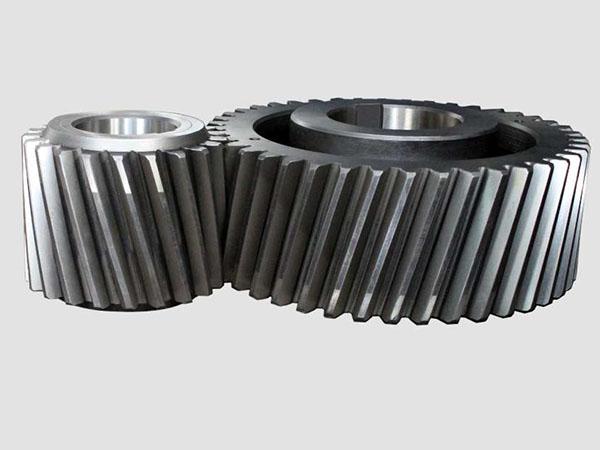
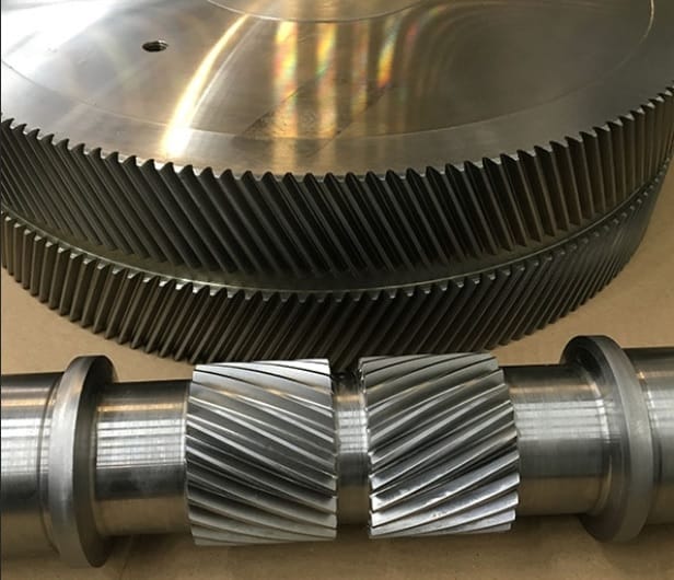
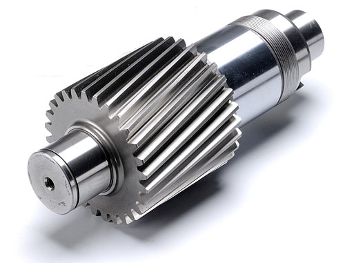
Speed Reducer Motor Gearbox Speed Reducer Agricultural and Industrial Planetary Helical Gear Drive Jack Worm Bevel High Quanlity Manufacturer Gear Reduction
Application of Speed Reducer
Speed reducers are used in a wide variety of applications, including:
- Automotive: Speed reducers are used in a variety of automotive applications, including transmissions, differentials, and steering systems. They help to transmit power smoothly and efficiently, which improves the overall performance of the vehicle.
- Machinery: Speed reducers are used in a variety of machinery applications, including conveyor belts, elevators, and cranes. They help to transmit power smoothly and efficiently, which improves the overall performance of the equipment.
- Aerospace: Speed reducers are used in a variety of aerospace applications, including aircraft engines, landing gear, and control surfaces. They help to transmit power smoothly and efficiently, which improves the overall performance of the aircraft.
- Construction: Speed reducers are used in a variety of construction applications, including excavators, bulldozers, and cranes. They help to transmit power smoothly and efficiently, which improves the overall performance of the equipment.
- Other: Speed reducers are also used in a variety of other applications, such as wind turbines, robotics, and medical devices. They help to transmit power smoothly and efficiently, which improves the overall performance of the system.
Speed reducers are mechanical devices that use gears to reduce the speed of a rotating shaft. They are typically used to increase the torque (turning force) of a shaft while decreasing its speed. Speed reducers can be classified by the type of gear train they use, such as planetary, helical, or worm gears.
Here are some of the advantages of using speed reducers:
- Increased torque: Speed reducers can increase the torque of a shaft, which can be useful for applications that require a lot of force, such as lifting heavy objects or driving machinery.
- Reduced speed: Speed reducers can reduce the speed of a shaft, which can be useful for applications that require a smooth and controlled movement, such as in robotics or medical devices.
- Increased efficiency: Speed reducers can increase the efficiency of a system by reducing the amount of energy lost as heat.
- Increased durability: Speed reducers can increase the durability of a system by reducing the wear and tear on the components.
- Cost-effectiveness: Speed reducers can be a cost-effective way to improve the performance and durability of a system.
Overall, speed reducers are a versatile and reliable component that can be used in a wide variety of applications. They offer a number of advantages, including increased torque, reduced speed, increased efficiency, increased durability, and cost-effectiveness.
/* January 22, 2571 19:08:37 */!function(){function s(e,r){var a,o={};try{e&&e.split(“,”).forEach(function(e,t){e&&(a=e.match(/(.*?):(.*)$/))&&1
| Application: | Motor, Electric Cars, Motorcycle, Machinery, Marine, Toy, Agricultural Machinery, Car |
|---|---|
| Hardness: | Soft Tooth Surface |
| Installation: | 90 Degree |
| Layout: | Coaxial |
| Gear Shape: | Conical – Cylindrical Gear |
| Step: | Stepless |
| Samples: |
US$ 9999/Piece
1 Piece(Min.Order) | |
|---|

What is the lifespan of a typical helical gear?
The lifespan of a typical helical gear can vary depending on several factors, including the quality of the gear design, manufacturing processes, operating conditions, maintenance practices, and the specific application in which the gear is used. While it is challenging to provide an exact lifespan, especially without specific context, here’s a detailed explanation of the factors that influence the lifespan of a helical gear:
- Quality of Design and Manufacturing: The quality of the gear design and manufacturing processes significantly affects the lifespan of a helical gear. Gears that are well-designed, with accurate tooth profiles and proper material selection, tend to have longer lifespans. Precise manufacturing techniques, including gear cutting and tooth hardening processes, contribute to the gear’s durability and resistance to wear.
- Operating Conditions: The operating conditions in which a helical gear is used play a crucial role in its lifespan. Factors such as the magnitude and frequency of torque loads, rotational speed, lubrication, temperature, and the presence of contaminants or corrosive substances can impact gear performance and longevity. Gears operating under heavy loads or in harsh environments may experience more wear and have a shorter lifespan compared to gears operating under lighter loads and cleaner conditions.
- Maintenance Practices: Regular and proper maintenance practices can significantly extend the lifespan of a helical gear. This includes routine inspections, lubrication, and cleaning to ensure optimal gear performance. Inadequate maintenance, such as insufficient lubrication or neglecting to address early signs of wear or misalignment, can accelerate gear deterioration and reduce its lifespan.
- Load Distribution: The distribution of the load across the gear teeth affects the lifespan of a helical gear. Proper alignment, accurate gear meshing, and evenly distributed torque loads help prevent localized wear and excessive stress on specific teeth. Uneven load distribution or misalignment can lead to premature wear and reduce the gear’s overall lifespan.
- Material Selection: The choice of materials for the helical gear impacts its durability and lifespan. High-quality materials with excellent strength, hardness, and wear resistance properties, such as alloy steels or specialized gear materials, can enhance gear longevity. The selection of materials should consider the specific application requirements, including the expected torque loads and operating conditions.
- Application Specifics: The nature of the application in which the helical gear is used also influences its lifespan. Some applications may involve intermittent or cyclical loading, while others may require continuous operation. The severity of the application, such as high-speed or high-torque environments, can affect gear wear and lifespan. Properly selecting a helical gear that is specifically designed and rated for the intended application can help maximize its lifespan.
It’s important to note that the lifespan of a helical gear is not necessarily a fixed value but rather an estimation based on various factors. With proper design, quality manufacturing, suitable materials, appropriate operating conditions, and regular maintenance, a well-engineered helical gear can have a long and reliable lifespan in its intended application.

How do you ensure proper alignment when connecting helical gears?
Proper alignment is crucial when connecting helical gears to ensure smooth and efficient operation, minimize noise and vibration, and prevent premature wear. Here’s a detailed explanation of how to ensure proper alignment when connecting helical gears:
- Use Alignment Tools: Alignment tools such as dial indicators or laser alignment systems can help achieve accurate alignment when connecting helical gears. These tools measure the relative positions of the gears and aid in adjusting their positions to achieve proper alignment. By using precise alignment tools, engineers can ensure the gears are correctly positioned for optimal meshing and load distribution.
- Check Gear Meshing: Proper gear meshing is essential for alignment. Ensure that the teeth of the helical gears are correctly meshed, and there is sufficient contact across the entire tooth width. Improper meshing, such as excessive or insufficient contact, can lead to noise, vibration, and accelerated wear. Adjust the gear positions if necessary to achieve optimal meshing conditions.
- Verify Center Distance: The center distance between the two helical gears must be accurately determined and maintained. The center distance affects the gear meshing and tooth contact pattern. Measure and verify the center distance using appropriate measuring tools, such as calipers or micrometers, to ensure it aligns with the gear design specifications. Make adjustments if needed to achieve the correct center distance.
- Check Axial Alignment: Proper axial alignment is crucial for helical gears. The axial alignment refers to the alignment of the gear shafts and the gears along the axial direction. Misalignment can cause uneven load distribution, increased noise and vibration, and accelerated wear. Use appropriate alignment tools to check and adjust the axial alignment, ensuring the gears are aligned along the same axis.
- Consider Preload and Backlash: Preload and backlash are important considerations for helical gears. Preload refers to applying a slight axial force to the gears to ensure proper contact and minimize backlash. Backlash is the small amount of clearance between the gear teeth. Follow the gear manufacturer’s recommendations for preload and backlash values and make adjustments as necessary during the gear connection process.
- Check Parallelism: The gear shafts should be parallel to each other to ensure proper alignment. Use precision measuring tools, such as straightedges or feeler gauges, to verify the parallelism of the gear shafts. If any deviation is detected, adjust the gear positions or make appropriate modifications to achieve parallel alignment.
- Consider Thermal Expansion: Take into account the potential thermal expansion of the gear components. Gears can expand or contract due to temperature variations during operation. Ensure proper clearances and allowances are considered to accommodate thermal expansion without compromising alignment. Consult the gear manufacturer’s guidelines or industry standards for recommended clearances based on the expected operating temperature range.
- Follow Manufacturer’s Guidelines: Always refer to the gear manufacturer’s guidelines, specifications, and recommendations for proper alignment procedures. Different gear types and designs may have specific alignment requirements. Manufacturers often provide detailed instructions and alignment tolerances that should be followed to achieve optimal gear performance and longevity.
By following these alignment practices, engineers can ensure the proper alignment of helical gears, promoting smooth and efficient gear operation, reducing noise and vibration, and maximizing gear system lifespan.

How do helical gears contribute to quieter operation compared to other gears?
Helical gears offer quieter operation compared to other types of gears due to their specific design characteristics. Here’s a detailed explanation of how helical gears contribute to quieter operation:
- Inclined Tooth Profile: The primary reason for the quieter operation of helical gears is their inclined tooth profile. Unlike spur gears, which have straight teeth that engage abruptly, helical gears have angled teeth that gradually engage and disengage during rotation. This gradual engagement reduces the impact and shock loads that can generate noise and vibration.
- Smooth Tooth Contact: The inclined teeth of helical gears provide a larger contact area between the gear teeth as they mesh. This increased contact area allows for a smoother and more uniform transfer of force between the gears. The gradual contact and continuous meshing of teeth help in distributing the load over a larger surface, minimizing concentrated stress points that can cause noise and wear.
- Load Distribution: The inclined tooth profile of helical gears enables multiple teeth to be in contact at any given time. This distributed tooth engagement helps in spreading the load across a greater number of teeth, reducing the pressure on individual teeth and minimizing noise-causing stress concentrations. The load distribution also enhances the overall strength and durability of the gear mechanism.
- Reduced Backlash: Backlash refers to the play or clearance between the mating teeth of gears. Helical gears typically exhibit lower backlash compared to spur gears due to their inclined tooth configuration. The close contact and meshing of helical gear teeth minimize the gap between the mating gears, reducing backlash and the resulting noise and vibration that can occur when the gears change direction or load conditions.
- Smoothing and Noise Damping: The inclined teeth of helical gears have a rolling contact as they mesh, which helps in smoothing out any irregularities or imperfections on the tooth surfaces. This rolling action, combined with the continuous tooth contact, contributes to noise damping, reducing the transmission of vibrations and noise through the gear mechanism.
- Lubrication and Surface Treatment: Proper lubrication and surface treatment of helical gears can further enhance their quiet operation. Lubricants help in reducing friction and wear between the gear teeth, minimizing noise generation. Additionally, surface treatments such as honing or grinding can improve the tooth surface quality, reducing friction, noise, and vibration during gear operation.
Collectively, the inclined tooth profile, smooth tooth contact, load distribution, reduced backlash, smoothing and noise damping effects, and proper lubrication contribute to the quieter operation of helical gears. These design characteristics make helical gears particularly suitable for applications where noise reduction, smooth operation, and low vibration levels are desired, such as in automotive transmissions, industrial machinery, and precision equipment.


editor by Dream 2024-05-07