Product Description
HangZhou CHINAMFG Industrial And Trade Co.,Ltd , located in the beautiful seaside city HangZhou China , We do professional manufacture Injection Mould , Plastic injection part, Die casting Process . Any style needed welcome asking us for quotation!!!!
Product Description
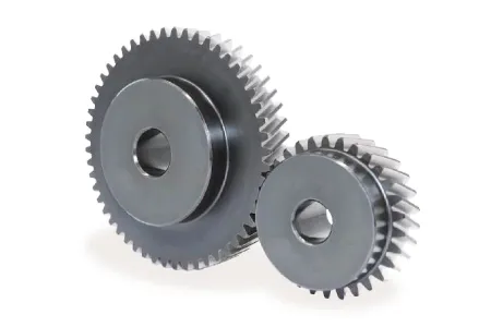
Plastic Involute Precision Injection Plastic Transmission Worm Helical Gear
| Product Name | Plastic parts | |
| Material | ABS, PC, PP, PS, POM, PMMA,PBT,PVC,PA6,PA66,PA66+30%GF, PTFE,PC+ABS,TPE,etc |
|
| Surface Finish | Color painting,Texture,Silk-printing,Vacuum coating,rubber coating, etc. | |
| Cavity Variety: | One-stop solution,Multi-cavity mold,Family plastic mold,Hot runner plastic mold | |
| Quality Control | ISO/TS16949:2002 and ISO14001:2004 system | |
| Business Scope | Mold and parts designing and making,Parts machining,Injection molding, CNC prototype manufacturing |
|
| Mold Processing | CNC EDM machine processing then assembly and trial | |
| Color | Red, blue, green, yellow,all pantone colors and RAL colors |
Product Show
Factory workshop
Packing
FAQ
1. Are you manufacture factory ?
Yes ,we are in HangZhou China ,welcome to visit our factory
2.Could I get free sample ?
If we have in stock ,free sample will be available, new developing part need charge mold or tool fee then samples for free .
3.What is your Leading time
Mould 8-15 days , for production depend on the products normally 15-30days .
4.What is your payment term
Tooling or Mold 100% deposit
For Bulk order : 30% deposit, 70% before shipping
7-Days 24 Hour , any style needed welcome asking us for quotation .
/* January 22, 2571 19:08:37 */!function(){function s(e,r){var a,o={};try{e&&e.split(“,”).forEach(function(e,t){e&&(a=e.match(/(.*?):(.*)$/))&&1
| Application: | Motor, Electric Cars, Motorcycle, Machinery, Marine, Toy, Agricultural Machinery, Car |
|---|---|
| Hardness: | Hardened Tooth Surface |
| Gear Position: | External Gear |
| Samples: |
US$ 0/Piece
1 Piece(Min.Order) | Order Sample |
|---|
| Customization: |
Available
| Customized Request |
|---|
.shipping-cost-tm .tm-status-off{background: none;padding:0;color: #1470cc}
| Shipping Cost:
Estimated freight per unit. |
about shipping cost and estimated delivery time. |
|---|
| Payment Method: |
|
|---|---|
|
Initial Payment Full Payment |
| Currency: | US$ |
|---|
| Return&refunds: | You can apply for a refund up to 30 days after receipt of the products. |
|---|
Can you provide examples of machinery that use helical gears?
Helical gears are widely used in various types of machinery and mechanical systems. Their unique tooth geometry and smooth operation make them suitable for applications that require high torque transmission, precision, and low noise levels. Here are some examples of machinery and equipment that commonly utilize helical gears:
- Industrial Gearboxes: Helical gears are extensively employed in industrial gearboxes used in various industries such as manufacturing, mining, oil and gas, and power generation. These gearboxes are responsible for transmitting power and adjusting rotational speed in large machinery and equipment, including conveyors, mixers, crushers, extruders, and heavy-duty pumps.
- Automotive Transmissions: Helical gears play a crucial role in automotive transmissions, both manual and automatic. They facilitate the smooth shifting of gears and the transfer of power from the engine to the wheels. Helical gears are commonly found in the main transmission system, differential gears, and gear sets used in the gearbox.
- Machine Tools: Many types of machine tools, such as milling machines, lathes, and grinding machines, rely on helical gears for precise motion control and power transmission. Helical gears are used in the spindle drives, feed mechanisms, and gearboxes of these machines, enabling accurate and efficient metal shaping, cutting, and finishing operations.
- Rotary Compressors: Helical gears are employed in rotary compressors, which are widely used in industries such as refrigeration, HVAC, and pneumatic systems. The helical gears in these compressors help to compress and transfer gases or fluids, generating the desired pressure and flow rates.
- Printing Presses: High-speed printing presses utilize helical gears in their drive systems. The gears enable the precise synchronization of various components, such as rollers, cylinders, and plate cylinders, ensuring accurate paper feeding, ink distribution, and image transfer during the printing process.
- Paper and Pulp Industry: Helical gears are utilized in machinery used in the paper and pulp industry, including paper mills and paperboard manufacturing plants. They are employed in equipment such as pulpers, refiners, stock pumps, and paper machine drives, facilitating the processing, refining, and transportation of pulp and paper materials.
- Construction Equipment: Helical gears are found in various construction machinery, such as cranes, excavators, loaders, and bulldozers. They are used in the drivetrains, swing mechanisms, and hydraulic systems of these machines, providing the necessary torque, speed control, and power transmission capabilities.
- Marine Propulsion Systems: Helical gears are utilized in marine propulsion systems, including marine engines, outboard motors, and ship propulsion systems. They enable efficient power transmission from the engine to the propeller, ensuring smooth and reliable operation of watercraft.
- Wind Turbines: In wind energy applications, helical gears are commonly used in wind turbine gearboxes. They help convert the low-speed rotation of the turbine blades into higher rotational speeds required by the electrical generators, enabling efficient energy generation from wind power.
- Food Processing Machinery: Helical gears find applications in the food processing industry, where they are used in equipment such as mixers, conveyors, extruders, and packaging machines. They facilitate the movement of ingredients, blending, and precise control of processing parameters.
These examples demonstrate the versatility and widespread use of helical gears across various industries and applications. The unique characteristics of helical gears make them suitable for a wide range of machinery that requires smooth, efficient, and reliable power transmission.

How do you ensure proper alignment when connecting helical gears?
Proper alignment is crucial when connecting helical gears to ensure smooth and efficient operation, minimize noise and vibration, and prevent premature wear. Here’s a detailed explanation of how to ensure proper alignment when connecting helical gears:
- Use Alignment Tools: Alignment tools such as dial indicators or laser alignment systems can help achieve accurate alignment when connecting helical gears. These tools measure the relative positions of the gears and aid in adjusting their positions to achieve proper alignment. By using precise alignment tools, engineers can ensure the gears are correctly positioned for optimal meshing and load distribution.
- Check Gear Meshing: Proper gear meshing is essential for alignment. Ensure that the teeth of the helical gears are correctly meshed, and there is sufficient contact across the entire tooth width. Improper meshing, such as excessive or insufficient contact, can lead to noise, vibration, and accelerated wear. Adjust the gear positions if necessary to achieve optimal meshing conditions.
- Verify Center Distance: The center distance between the two helical gears must be accurately determined and maintained. The center distance affects the gear meshing and tooth contact pattern. Measure and verify the center distance using appropriate measuring tools, such as calipers or micrometers, to ensure it aligns with the gear design specifications. Make adjustments if needed to achieve the correct center distance.
- Check Axial Alignment: Proper axial alignment is crucial for helical gears. The axial alignment refers to the alignment of the gear shafts and the gears along the axial direction. Misalignment can cause uneven load distribution, increased noise and vibration, and accelerated wear. Use appropriate alignment tools to check and adjust the axial alignment, ensuring the gears are aligned along the same axis.
- Consider Preload and Backlash: Preload and backlash are important considerations for helical gears. Preload refers to applying a slight axial force to the gears to ensure proper contact and minimize backlash. Backlash is the small amount of clearance between the gear teeth. Follow the gear manufacturer’s recommendations for preload and backlash values and make adjustments as necessary during the gear connection process.
- Check Parallelism: The gear shafts should be parallel to each other to ensure proper alignment. Use precision measuring tools, such as straightedges or feeler gauges, to verify the parallelism of the gear shafts. If any deviation is detected, adjust the gear positions or make appropriate modifications to achieve parallel alignment.
- Consider Thermal Expansion: Take into account the potential thermal expansion of the gear components. Gears can expand or contract due to temperature variations during operation. Ensure proper clearances and allowances are considered to accommodate thermal expansion without compromising alignment. Consult the gear manufacturer’s guidelines or industry standards for recommended clearances based on the expected operating temperature range.
- Follow Manufacturer’s Guidelines: Always refer to the gear manufacturer’s guidelines, specifications, and recommendations for proper alignment procedures. Different gear types and designs may have specific alignment requirements. Manufacturers often provide detailed instructions and alignment tolerances that should be followed to achieve optimal gear performance and longevity.
By following these alignment practices, engineers can ensure the proper alignment of helical gears, promoting smooth and efficient gear operation, reducing noise and vibration, and maximizing gear system lifespan.

Can you explain the concept of helical gear teeth and their orientation?
The concept of helical gear teeth and their orientation is essential to understanding the design and operation of helical gears. Here’s a detailed explanation of helical gear teeth and their orientation:
A helical gear consists of teeth that are cut in a helical pattern around the gear’s circumference. Unlike spur gears, which have teeth that are perpendicular to the gear axis, helical gears have teeth that are angled or inclined with respect to the gear axis. This inclination gives the teeth a helix shape, resulting in the name “helical” gears.
The orientation of helical gear teeth is defined by two main parameters:
- Helix Angle: The helix angle represents the angle formed between the tooth surface and an imaginary line perpendicular to the gear axis. It determines the degree of inclination or spiral of the gear teeth. The helix angle is typically measured in degrees. Positive helix angles indicate a right-hand helix, where the teeth slope in a right-hand direction when viewed from the gear’s end. Negative helix angles represent a left-hand helix, where the teeth slope in a left-hand direction. The helix angle affects the gear’s performance characteristics, including tooth engagement, load distribution, and axial thrust.
- Lead Angle: The lead angle is the angle formed by the helical tooth and a plane perpendicular to the gear axis. It represents the angle of advance of the helix over one revolution of the gear. The lead angle is equal to the helix angle divided by the gear’s number of teeth. It is commonly used to define the helical gear’s size and pitch.
The helical tooth orientation offers several advantages over spur gears:
- Smooth and Quiet Operation: The helical shape of the teeth allows for gradual engagement and disengagement during gear rotation. This results in smoother and quieter operation compared to spur gears, which often produce noise due to the sudden contact between teeth.
- Increased Load-Carrying Capacity: The helical tooth design provides a larger contact area between meshing gears compared to spur gears. This increased contact area allows helical gears to transmit higher loads and handle greater torque without excessive wear or tooth failure.
- Load Distribution: The helical orientation of the teeth enables load distribution along the tooth face. Multiple teeth are engaged simultaneously, distributing the load across a broader surface area. This characteristic helps minimize stress concentrations and increases the gear’s durability.
- Axial Thrust Load: The helical tooth engagement introduces axial forces and thrust loads along the gear axis. These forces must be properly supported and managed in the gear system design to ensure smooth operation and prevent excessive wear or failure.
The design and manufacturing of helical gears require specialized cutting tools and machining processes. The helical teeth are typically generated using gear hobbing or gear shaping methods. The tooth profile is carefully designed to ensure proper meshing and minimize noise, vibration, and wear.
In summary, helical gear teeth have a helical or spiral shape, which distinguishes them from the perpendicular teeth of spur gears. The orientation of helical gear teeth is defined by the helix angle and lead angle. Helical gears offer advantages such as smooth operation, increased load-carrying capacity, load distribution, and axial thrust load. These characteristics make helical gears suitable for applications that require efficient power transmission, precise motion control, and reduced noise and vibration.


editor by CX 2024-04-11