Product Description
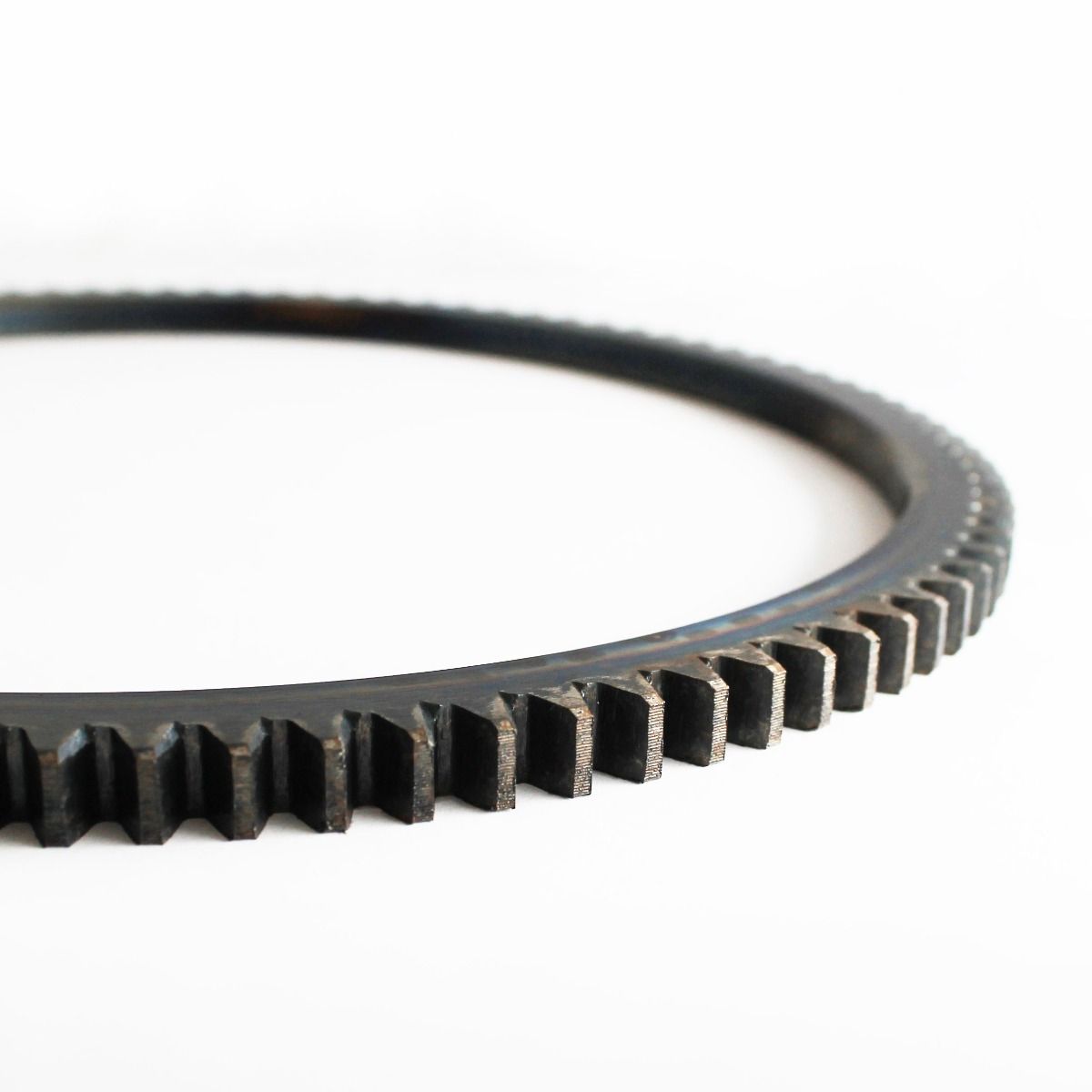
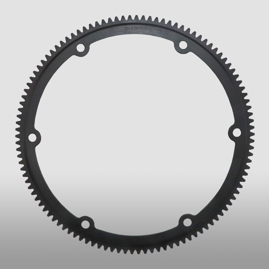
Pinion Rack Round Worm Screw Helical Hypoid Straight Ring Spiral Forged Bevel Spur Differential Steering Internal Box Spline Plastic Nylon Stainless Steel Gear
Gears:
The processing production line we see can produce the following gears: spur gears, helical gears, bevel gears, spiral bevel gears, straight bevel gears, internal gears, worm gears, gear rack
| Process | CNC machining,CNC milling, cnc lathe machining |
| Available Material | 1.Stainless Steel: SS201, SS303, SS304, SS316, SS416, SS420,etc. |
| 2.Steel: C45, 40Cr, 42CrMo, 20CrNiMo, 20CrMnTi, etc. (AISI 1045, 5140, 4140/4142, 8620 etc.) | |
| 3. Brass:C36000 ( C26800), C37700 ( HPb59), C38500( HPb58), C27200CuZn37), C28000(CuZn40),etc. | |
| 4.Bronze: C51000, C52100, C54400, etc. | |
| 5. Iron: 1213, 12L14,1215,etc. | |
| 6. Aluminum: Al6061, Al6063,Al2571,Al7075 etc | |
| 7. Carbon steel:AISI1006,AISI1571,AISI1571,etc. | |
| 8.Nylon PA66,MC901,POM plastic ects | |
| Hardness | HRC50~55 |
| Quality Control | ISO9001 and ISO14001 |
| Dimension bore tolerances | -/+0.01mm |
| Quality standard | AGMA, JIS, DIN |
| Size/Color | Gears and parts dimensions are according to drawings from customer, and colors are customized |
| Surface treatment | black oxide,Zn-plated,ni-plated,tin-plated,chrome plated,passivated,sandblast and anodize,chromate,polish,electro painting,black anodize,plain,H.D.G,etc. |
| Dimensions Tolerance | ±0.01mm or more precise |
| Samples confirmation and approval | samples shipped for confirmation and shipping cost paid by customers |
| Package | Inner clear plastic bag/outside carton/wooden pallets/ or any other special package as per customer’s requirements. |
We also have injection molding machines, which can produce plastic nylon gears according to your needs
Related products
Transmission products:
Gearbox/gear reducer:
Click here for more details!
Customization process
Support Customized Gears from Customers’ drawings and samples and Various non-standard customization
1.Products Discussions
Customers send drawings oramples, and quote according to customers’ requirements.
2.Molds designing
Designing 3D drawings and optimizing the products.
3.Drawing confirmation
Sending the mold drawing tothe customers , and the customers CHINAMFG for confirmation.
4.Molds Construction
Manufacture molds accurately and accurately according to the drawings.
5.Moulds Inspection and Moulds Test
Detect various indicators of molds and optimization of inner cavities.
6.Sample Aprroval from Customer
Customers approve the samples and confirm them for bulk production.
7.Mass Production
Bulk production according to customers’s PO
8.PO Finished
Shipping to the customer andthe customers receive the gears.
If you need other customized requirements, please click here to contact us!
Why Choose Us
We enthusiastically provide sincere and prompt service to our customers and establish sustainable business relationship with them.
100% Factory inspection, we are responsible for any problems subjected to malfunction in warranty period.
We Can Provide You:
- On-time Delivery with More Choice
- Product Solutions and Service
- Long Quality Guarantee
- Local Technical Support
- Fast Response to Customers’ Feedbacks in 24 hours
Also I would like to take this opportunity to give a brief introduction of our CHINAMFG company:
Our company is a famous manufacturer of agriculture gearbox,worm reduce gearbox, PTO shafts, Sprockets ,rollar chains, bevel gear, pulleys and racks in china.
We have exported many products to our customers all over the world, we have long-time experience and strong technology support.
You also can check our website to know for more details, if you need our products catalogue, please contact with us.
Company information
/* January 22, 2571 19:08:37 */!function(){function s(e,r){var a,o={};try{e&&e.split(“,”).forEach(function(e,t){e&&(a=e.match(/(.*?):(.*)$/))&&1
| Application: | Motor, Electric Cars, Motorcycle, Machinery, Marine, Toy, Agricultural Machinery, Car |
|---|---|
| Hardness: | Hardened Tooth Surface |
| Gear Position: | External Gear |
| Manufacturing Method: | Cast Gear |
| Toothed Portion Shape: | Bevel Wheel |
| Material: | Cast Iron |
| Samples: |
US$ 999/Piece
1 Piece(Min.Order) | |
|---|
How do you install a ring gear system?
Installing a ring gear system requires careful attention to ensure proper alignment, engagement, and secure attachment. Here’s a detailed explanation of the installation process:
- Prepare the Components: Gather all the necessary components for the ring gear system installation, including the ring gear, driving gear, and any other associated gears or components.
- Clean the Surfaces: Thoroughly clean the mounting surfaces of the gears and the mating components to remove any dirt, debris, or old lubricant. Clean surfaces will ensure better engagement and prevent contamination of the gear system.
- Inspect the Gears: Carefully inspect the ring gear and other gears for any signs of damage, wear, or misalignment. Check the teeth for any chips, cracks, or irregularities that may affect the performance of the gear system. Replace any damaged or worn gears before proceeding with the installation.
- Ensure Proper Alignment: Align the ring gear and the driving gear in the desired configuration. The alignment depends on the specific gear system and application requirements. Follow the manufacturer’s guidelines or engineering specifications to achieve the correct alignment.
- Establish Gear Engagement: Position the driving gear in close proximity to the ring gear and ensure proper engagement of the gear teeth. The teeth should mesh smoothly and evenly without any gaps or interference. Adjust the positioning of the gears if necessary to achieve optimal engagement.
- Secure Attachment: Once the gears are properly aligned and engaged, secure the ring gear in place. This may involve bolting or fastening the ring gear to a stationary component or housing. Follow the recommended torque specifications provided by the manufacturer to ensure proper tightening without overloading the gear system.
- Check Clearance and Backlash: Verify that there is adequate clearance between the gears and other nearby components to prevent interference during operation. Also, check the backlash, which is the slight gap between the meshing teeth, to ensure it falls within the recommended range. Adjust the gear positioning if clearance or backlash is outside the acceptable limits.
- Apply Lubrication: Apply the appropriate lubricant to the gear teeth and the mating surfaces to reduce friction and wear. Refer to the manufacturer’s recommendations for the type and amount of lubricant to use. Proper lubrication is crucial for smooth gear operation and longevity.
- Perform Function and Safety Tests: After the installation, perform function tests to ensure the gear system operates smoothly and without any abnormal noise or vibration. Additionally, check for any safety considerations, such as the presence of appropriate guards or protective covers if required for the specific application.
It’s important to note that the installation process may vary depending on the specific gear system, machinery, and manufacturer’s guidelines. Always refer to the provided instructions and consult with experts or professionals if needed to ensure a proper and accurate installation of the ring gear system.
Are ring gears suitable for high-torque applications?
Ring gears are indeed suitable for high-torque applications. Here’s a detailed explanation of why ring gears are suitable for high-torque applications:
Ring gears are designed to handle high torque loads and are commonly used in various applications that require substantial torque transmission. Here are the reasons why ring gears are well-suited for high-torque applications:
- Robust Construction: Ring gears are typically constructed with robust materials, such as hardened steel or other high-strength alloys. This construction provides the necessary strength, durability, and resistance to withstand high torque forces without deformation or failure.
- Large Contact Area: Ring gears have a large contact area between their gear teeth, which allows for efficient power transmission and load distribution. The larger contact area enables the ring gear to transmit higher torque without experiencing excessive stress concentrations or localized overloading.
- Optimized Tooth Geometry: The tooth geometry of ring gears is designed to handle high torque. The shape and profile of the gear teeth are optimized to distribute the torque load evenly, minimizing stress concentrations and enhancing the gear’s ability to transmit higher torque without premature wear or failure.
- Multiple Gear Engagements: Ring gears often engage with multiple gears or pinions, which further enhances their torque capacity. The engagement of multiple gears allows for load sharing, distributing the torque across multiple contact points and reducing the strain on individual gear teeth.
- Customizable Gear Ratios: Ring gears can be designed with various gear ratios to meet specific torque requirements. By adjusting the tooth count or diameter of the ring gear and mating gears, the gear system can be optimized for high torque applications while maintaining the desired speed or rotational characteristics.
- Used in Heavy-Duty Applications: Ring gears are widely used in heavy-duty applications that demand high torque transmission. Examples include automotive differentials, industrial gearboxes, mining equipment, construction machinery, and wind turbines. These applications rely on ring gears to effectively transmit and handle the high torque generated by powerful engines, motors, or turbines.
It’s important to note that while ring gears are suitable for high-torque applications, proper engineering analysis and selection should be carried out to ensure that the specific design, material, and size of the ring gear are appropriate for the intended torque requirements. Factors such as gear tooth strength, gear geometry, material properties, lubrication, and operating conditions should be carefully considered to ensure reliable and efficient performance in high-torque applications.
What is a ring gear and how does it work?
A ring gear is a type of gear that features teeth on the outer perimeter of a circular ring-shaped component. It is commonly used in various mechanical systems and applications. Here’s a detailed explanation of what a ring gear is and how it works:
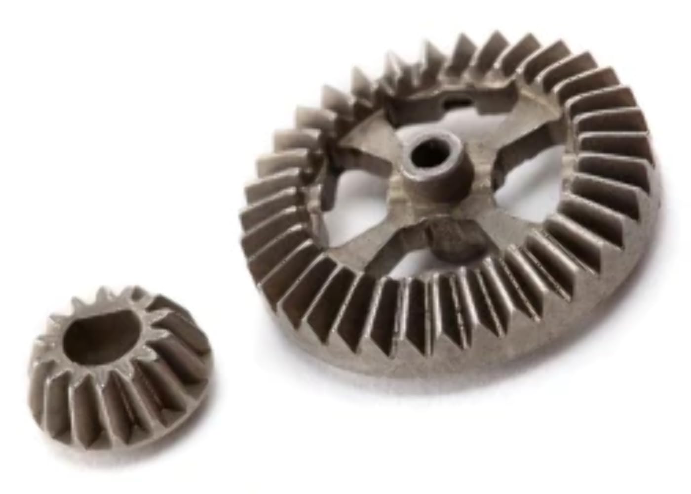
A ring gear, also known as an annular gear or internal gear, is a gear with teeth on the inside circumference of a circular ring. It is designed to mesh with a pinion gear or another gear that has teeth on the outside. The combination of a ring gear and a pinion gear forms a gear set, enabling the transmission of rotational motion and torque between the two gears.
Here’s how a ring gear works:
- Tooth Engagement: When a ring gear and a pinion gear are brought together, the teeth of the pinion gear mesh with the teeth of the ring gear. The teeth of the pinion gear enter the spaces between the teeth of the ring gear, creating a mechanical connection between the two gears.
- Motion Transmission: As the driving gear (such as the pinion gear) rotates, it transfers rotational motion to the ring gear. The teeth of the driving gear push against the teeth of the ring gear, causing the ring gear to rotate in the opposite direction. This rotational motion can be used to drive other components or systems connected to the ring gear.
- Torque Transfer: The meshing of the teeth between the ring gear and the driving gear allows for the transfer of torque. Torque is the rotational force or twisting force applied to a gear. As the driving gear exerts torque on the ring gear through the meshing teeth, the ring gear experiences a torque load. This torque load can be transmitted to other components or systems connected to the ring gear.
- Gear Ratio: The gear ratio between the ring gear and the driving gear determines the speed and torque relationship between the two gears. The gear ratio is defined as the ratio of the number of teeth on the ring gear to the number of teeth on the driving gear. By changing the size or number of teeth on either the ring gear or the driving gear, the gear ratio can be adjusted to achieve the desired speed or torque output.
- Load Distribution: The ring gear distributes the load over a larger area compared to other types of gears. This load distribution characteristic allows the ring gear to handle higher loads and torque. The design of the ring gear and its tooth profile ensures that the load is evenly distributed across the surface of the gear, enhancing its durability and reducing the risk of premature wear or failure.
Ring gears are commonly used in various applications, including automotive transmissions, differential systems, planetary gear systems, industrial machinery, and power transmission equipment. They provide advantages such as compactness, high torque capacity, load distribution, and the ability to achieve high gear ratios.
It’s important to note that the design and characteristics of ring gears may vary depending on the specific application and requirements. Factors such as tooth profile, material selection, lubrication, and manufacturing techniques are carefully considered to ensure optimal performance and durability of the ring gear.


editor by CX 2024-03-26