Product Description
About Fenghe
Provide customized industry solutions for you
- 17 years producing experience, strict quality control can be the industry’s best solution guarantee.
-
China leading supplier for slewing bearing,the products have through ISO 9001,CAPE certifiaction,have more than 50 product patents.
- Excellence in Quality and Precision Performance are constant hallmarks of all FENGHE products. Dialogue with the customer and a flexibility of approach combine with responsive design and development innovations to ensure superior delivery.
R&D/Maintenance
Engineers in Fenghe slewing bearing have an experience in turntable bearing over 17 years, they developed the R&D team and testing lab, continuous to making it extra stable and precision during the operation, Fenghe brand provide the best solution according to each customer with tailored products with many thousands of attempting.
Test
Life test
Application test
Environmental impacting test
Torque test
Vibration test
Measurement, inspection and analysis
Coordinate measuring machine (CMM)
Magnetic particle flaw detector (MT)
Ultrasonic detector (UT)
ScHangZhou electron microscope (SEM)
HDR digital microscope
Rockwell hardness
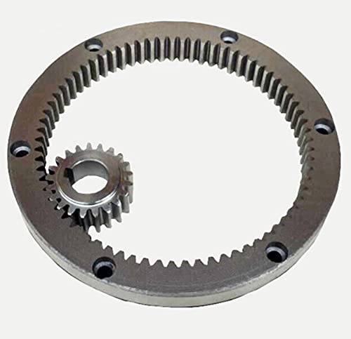
Product types
| Own 20,000 production facility and 10,000 forging workshop. Heat treated 6 times throughout production. Model No.:012.40.1120 Types of our products:
|
||||||||||||||||||||||||||||||||||||||||||||||||||||||||||||||||||||||||||||||||||||||||||||||||||||||||||||||||||||||||||||||||||||||||||||||||||||||||||||||||||||||||||||||||||||||||||||||||||||||||||||||||||||||||||||||||||||||||||||||||||||||||||||||||||||||||||||||||||||||||||||||||||||||||||||||||||||||||||||||||||||||||||||||||||||||||||||||||||||||||||||||||||||||||||||||||||||||||||||||||||||||||||||||||||||||||||||||||||||||||||||||||||||||||||||||||||||||||||||||||||||||||||||||||||||||||||||||||||||||||||||||||||||||||||||||||||||||||||||||||||||||||||||||||||
Examples of use
Fenghe slewing bearings can even be used in the most demanding scopes of application.
We are committed to providing various standard and non-standard slewing bearing solutions for the machinery industry. If you have more questions forslewing rings and table bearings assembling, our in house engineers will pay attention to this parts and provide solutions to you.
Fenghe slewing bearings are widely applicationto the machinery industry and provide excellent precision for smoothly running. We do a lot of job in reducing weight, creating space, reducing friction and extending durable life. Fenghe offers a variety of raw materials, internal assembling, grease and corrosion resistance options. Fenghe offers the widest range of slewing bearings with P.C.D of 120mm to 5500mm.
Fenghe slewing ring is suitable for all kinds of harsh environments. Our technical research and development personnel focus on sealing protection during the slewing bearing operation, which effectively guarantees the internal lubrication of the slewing ring and prolongs the durable life.
| NO. | Internal Gear DL mm | Dimensions | Mounting dimensions | Structural dimensions | Gear data | Gear circumferential force | weig ht kg | ||||||||||||||||
| D mm | d mm | H mm | D1 mm | D2 mm | n | mm | dm mm | L mm | n1 mm | D3 mm | d1 mm | H1 mm | h mm | b mm | x | M mm | De mm | z | Norma lizing Z 104N | Quen ching T 104N | |||
| 1 | 013.25.315 | 408 | 222 | 70 | 372 | 258 | 20 | 18 | M16 | 32 | 2 | 316 | 314 | 60 | 10 | 50 | 0 | 5 | 190 | 40 | 2.9 | 4.4 | |
| 2 | 013.25.355 | 448 | 262 | 70 | 412 | 298 | 20 | 18 | M16 | 32 | 2 | 356 | 354 | 60 | 10 | 50 | 0 | 5 | 235 | 49 | 2.9 | 4.4 | |
| 3 | 013.25.400 | 493 | 307 | 70 | 457 | 343 | 20 | 18 | M16 | 32 | 2 | 401 | 399 | 60 | 10 | 50 | 0 | 6 | 276 | 48 | 3.5 | 5.3 | |
| 4 | 013.25.450 | 543 | 357 | 70 | 507 | 393 | 20 | 18 | M16 | 32 | 2 | 451 | 449 | 60 | 10 | 50 | 0 | 6 | 324 | 56 | 3.5 | 5.3 | |
| 5 | 013.30.500 | 602 | 398 | 80 | 566 | 434 | 20 | 18 | M16 | 32 | 4 | 501 | 498 | 70 | 10 | 60 | 1 | 5 | 367 | 74 | 3.7 | 5.2 | 85 |
| 014.30.500 | 6 | 368 | 62 | 4.5 | 6.2 | ||||||||||||||||||
| 5′ | 013.25.500 | 602 | 398 | 80 | 566 | 434 | 20 | 18 | M16 | 32 | 4 | 501 | 499 | 70 | 10 | 60 | 1 | 5 | 367 | 74 | 3.7 | 5.2 | 85 |
| 014.25.500 | 6 | 368 | 62 | 4.5 | 6.2 | ||||||||||||||||||
| 6 | 013.30.560 | 662 | 458 | 80 | 626 | 494 | 20 | 18 | M16 | 32 | 4 | 561 | 558 | 70 | 10 | 60 | 1 | 5 | 427 | 86 | 3.7 | 5.2 | 95 |
| 014.30.560 | 6 | 428 | 72 | 4.5 | 6.2 | ||||||||||||||||||
| 6′ | 013.25.560 | 662 | 458 | 80 | 626 | 494 | 20 | 18 | M16 | 32 | 4 | 561 | 559 | 70 | 10 | 60 | 1 | 5 | 427 | 86 | 3.7 | 5.2 | 95 |
| 014.25.560 | 6 | 428 | 72 | 4.5 | 6.2 | ||||||||||||||||||
| 7 | 013.30.630 | 732 | 528 | 80 | 696 | 564 | 24 | 18 | M16 | 32 | 4 | 631 | 628 | 70 | 10 | 60 | 1 | 6 | 494 | 83 | 4.5 | 6.2 | 110 |
| 014.30.630 | 8 | 491 | 62 | 6 | 8.3 | ||||||||||||||||||
| 7′ | 013.25.630 | 732 | 528 | 80 | 696 | 564 | 24 | 18 | M16 | 32 | 4 | 631 | 629 | 70 | 10 | 60 | 1 | 6 | 494 | 83 | 4.5 | 6.2 | 110 |
| 014.25.630 | 8 | 491 | 62 | 6 | 8.2 | ||||||||||||||||||
| 8 | 013.30.710 | 812 | 608 | 80 | 776 | 644 | 24 | 18 | M16 | 32 | 4 | 711 | 708 | 70 | 10 | 60 | 1 | 6 | 572 | 96 | 4.5 | 6.2 | 120 |
| 014.30.710 | 8 | 571 | 72 | 6 | 8.3 | ||||||||||||||||||
| 8′ | 013.25.710 | 812 | 608 | 80 | 776 | 644 | 24 | 18 | M16 | 32 | 4 | 711 | 709 | 70 | 10 | 60 | 1 | 6 | 572 | 96 | 4.5 | 6.2 | 120 |
| 014.25.710 | 8 | 571 | 72 | 6 | 8.9 | ||||||||||||||||||
| 9 | 013.40.800 | 922 | 678 | 100 | 878 | 722 | 30 | 22 | M20 | 40 | 6 | 801 | 798 | 90 | 10 | 80 | 1 | 8 | 635 | 80 | 8 | 11.1 | 220 |
| 014.40.800 | 10 | 634 | 64 | 10 | 14 | ||||||||||||||||||
| 9′ | 013.30.800 | 922 | 678 | 100 | 878 | 722 | 30 | 22 | M20 | 40 | 6 | 801 | 798 | 90 | 10 | 80 | 1 | 8 | 635 | 80 | 8 | 11.1 | 220 |
| 014.30.800 | 10 | 634 | 64 | 10 | 14.1 | ||||||||||||||||||
| 10 | 013.40.900 | 1571 | 778 | 100 | 978 | 822 | 30 | 22 | M20 | 40 | 6 | 901 | 898 | 90 | 10 | 80 | 1 | 8 | 739 | 93 | 8 | 11.1 | 240 |
| 014.40.900 | 10 | 734 | 74 | 10 | 14 | ||||||||||||||||||
| 10′ | 013.30.900 | 1571 | 778 | 100 | 978 | 822 | 30 | 22 | M20 | 40 | 6 | 901 | 898 | 90 | 10 | 80 | 1 | 8 | 739 | 93 | 8 | 11.1 | 240 |
| 014.30.900 | 10 | 734 | 74 | 10 | 14 | ||||||||||||||||||
| 11 | 013.40.1000 | 1122 | 878 | 100 | 1078 | 922 | 36 | 22 | M20 | 40 | 6 | 1001 | 998 | 90 | 10 | 80 | 1 | 10 | 824 | 83 | 10 | 14 | 270 |
| 014.40.1000 | 12 | 821 | 69 | 12 | 16.7 | ||||||||||||||||||
| 11′ | 013.30.1000 | 1122 | 878 | 100 | 1078 | 922 | 36 | 22 | M20 | 40 | 6 | 1001 | 998 | 90 | 10 | 80 | 1 | 10 | 824 | 83 | 10 | 14 | 270 |
| 014.30.1000 | 12 | 821 | 69 | 12 | 16.7 | ||||||||||||||||||
| 12 | 013.40.1120 | 1242 | 998 | 100 | 1198 | 1042 | 36 | 22 | M20 | 40 | 6 | 1121 | 1118 | 90 | 10 | 80 | 1 | 10 | 944 | 95 | 10 | 14 | 300 |
| 014.40.1120 | 12 | 941 | 79 | 12 | 16.7 | ||||||||||||||||||
| 12′ | 013.30.1120 | 1242 | 998 | 100 | 1198 | 1042 | 36 | 22 | M20 | 40 | 6 | 1121 | 1118 | 90 | 10 | 80 | 1 | 10 | 944 | 95 | 10 | 14 | 300 |
| 014.30.1120 | 12 | 941 | 79 | 12 | 16.7 | ||||||||||||||||||
| 13 | 013.45.1250 | 1390 | 1110 | 110 | 1337 | 1163 | 40 | 26 | M24 | 48 | 5 | 1252 | 1248 | 100 | 10 | 90 | 1 | 12 | 1049 | 88 | 13.5 | 18.8 | 420 |
| 014.45.1250 | 14 | 1042 | 75 | 15.8 | 21.9 | ||||||||||||||||||
| 13′ | 013.35.1250 | 1390 | 1110 | 110 | 1337 | 1163 | 40 | 26 | M24 | 48 | 5 | 1251 | 1248 | 100 | 10 | 90 | 1 | 12 | 1049 | 88 | 13.5 | 18.8 | 420 |
| 014.35.1250 | 14 | 1042 | 75 | 15.8 | 21.9 | ||||||||||||||||||
| 14 | 013.45.1400 | 1540 | 1260 | 110 | 1487 | 1313 | 40 | 26 | M24 | 48 | 5 | 1402 | 1398 | 100 | 10 | 90 | 1 | 12 | 1193 | 100 | 13.5 | 18.8 | 480 |
| 014.45.1400 | 14 | 1196 | 86 | 15.5 | 21.9 | ||||||||||||||||||
| 14′ | 013.35.1400 | 1540 | 1260 | 110 | 1487 | 1313 | 40 | 26 | M24 | 48 | 5 | 1401 | 1398 | 100 | 10 | 90 | 1 | 12 | 1193 | 100 | 13.5 | 18.8 | 480 |
| 014.35.1400 | 14 | 1196 | 86 | 15.8 | 21.9 | ||||||||||||||||||
| 15 | 013.45.1600 | 1740 | 1460 | 110 | 1687 | 1513 | 45 | 26 | M24 | 48 | 5 | 1602 | 1598 | 100 | 10 | 90 | 1 | 14 | 1392 | 100 | 15.8 | 21.9 | 550 |
| 014.45.1600 | 16 | 1382 | 87 | 18.1 | 25 | ||||||||||||||||||
| 15′ | 013.35.1600 | 1740 | 1460 | 110 | 1687 | 1513 | 45 | 26 | M24 | 48 | 5 | 1601 | 1598 | 100 | 10 | 90 | 1 | 14 | 1392 | 100 | 15.8 | 21.9 | 55, 0 |
| 014.35.1600 | 16 | 1382 | 87 | 18 | 25 | ||||||||||||||||||
/* March 10, 2571 17:59:20 */!function(){function s(e,r){var a,o={};try{e&&e.split(“,”).forEach(function(e,t){e&&(a=e.match(/(.*?):(.*)$/))&&1
| Application: | Machinery |
|---|---|
| Hardness: | Hardened Tooth Surface |
| Gear Position: | External Gear |
| Toothed Portion Shape: | Spur Gear |
| Material: | 50mn, 42CrMo, Gcr15 |
| Type: | Circular Gear |
| Customization: |
Available
| Customized Request |
|---|
What is the purpose of using ring gears in machinery?
Ring gears serve multiple purposes and offer various advantages when used in machinery. Here’s a detailed explanation of the purpose of using ring gears:
- Power Transmission: One of the primary purposes of ring gears in machinery is to facilitate power transmission. Ring gears, along with other meshing gears, transmit torque and rotational motion from the driving gear to the driven components or systems. They enable the transfer of power from a power source to various parts of the machinery, driving the movement and operation of different mechanisms and processes.
- Gear Ratio Control: Ring gears allow for precise control over the gear ratio in machinery. By adjusting the size of the ring gear and its meshing gears, different gear ratios can be achieved. Gear ratios determine the relationship between the rotational speeds and torques of the driving and driven gears. This ability to control the gear ratio enables machinery to operate at desired speeds, optimize torque output, and adapt to specific application requirements.
- Mechanical Advantage: Ring gears provide a mechanical advantage in machinery. By leveraging the gear ratio control mentioned above, ring gears can amplify or reduce the torque output of the power source. This mechanical advantage allows machinery to generate higher forces or torques than the original power source alone. It enables the machinery to handle heavy loads, perform tasks requiring significant force, and enhance overall operational efficiency.
- Load Distribution: Ring gears contribute to load distribution within machinery. The meshing teeth of the ring gear engage with multiple teeth of other gears, distributing the transmitted loads across these meshing points. This load distribution helps prevent excessive stress concentration on specific gear teeth, ensuring even wear and reducing the risk of gear failure. By distributing the load, ring gears enhance the overall durability and reliability of the machinery.
- Motion Control: Ring gears play a crucial role in motion control within machinery. By transmitting rotational motion, ring gears enable precise movement and synchronization of various components and mechanisms. They ensure that different parts of the machinery operate in a coordinated manner, allowing for smooth and controlled motion. Ring gears contribute to accurate positioning, speed regulation, and overall motion precision in machinery.
- Compact Design: Ring gears offer a compact design solution. Due to their annular shape, they can be integrated into machinery with limited space. The compactness of ring gears is particularly beneficial in applications where space constraints are a concern. Their small footprint allows for efficient use of available space, enabling the design of more compact and lightweight machinery without sacrificing power transmission capabilities.
- Versatile Applications: Ring gears find wide applications across various industries and machinery types. They are used in automotive transmissions, industrial machinery, robotics, aerospace systems, power generation equipment, and more. The versatility of ring gears stems from the ability to configure them in different types, such as external or internal ring gears, helical gears, or bevel gears. This versatility makes ring gears adaptable to a wide range of machinery designs and requirements.
By serving these purposes, ring gears contribute to the efficient and reliable operation of machinery. They enable power transmission, gear ratio control, mechanical advantage, load distribution, motion control, and compact design, making them essential components in various mechanical systems.
What is the lifespan of a typical ring gear?
The lifespan of a typical ring gear can vary depending on various factors. Here’s a detailed explanation of the factors that influence the lifespan of a ring gear:
The lifespan of a ring gear is influenced by several factors, including:
- Material Quality: The quality of the material used to manufacture the ring gear plays a significant role in its lifespan. High-quality materials with good mechanical properties, such as hardened steel or alloys with high wear resistance, tend to have longer lifespans compared to lower-quality materials.
- Design and Load Conditions: The design of the ring gear, including its tooth profile, dimensions, and load-bearing capacity, affects its lifespan. Ring gears designed to handle higher loads and stresses are likely to have longer lifespans. The operating conditions, such as the magnitude and frequency of the torque loads, also impact the lifespan of the ring gear.
- Maintenance and Lubrication: Proper maintenance and lubrication are essential for preserving the lifespan of a ring gear. Regular inspection, cleaning, and lubrication of the gear system help reduce wear and prevent damage. Inadequate maintenance or the use of improper lubricants can accelerate wear and shorten the lifespan of the ring gear.
- Operating Environment: The operating environment in which the ring gear operates affects its lifespan. Factors such as temperature extremes, humidity, contaminants, and exposure to corrosive substances can impact the material integrity and performance of the ring gear. Harsh operating environments may lead to accelerated wear and reduced lifespan.
- Application-Specific Factors: The specific application in which the ring gear is used can influence its lifespan. Some applications may subject the ring gear to severe operating conditions, high-speed rotations, frequent starts and stops, or heavy shock loads, which can affect its durability and longevity. The accuracy of gear alignment, proper installation, and any additional factors specific to the application should be considered to assess the ring gear’s lifespan.
Given these factors, it is challenging to provide a specific lifespan for a typical ring gear. Lifespan estimates can range from tens of thousands to hundreds of thousands or even millions of operating cycles or hours of operation. The longevity of a ring gear can be extended through proper selection of materials, careful design, routine maintenance, and adherence to recommended operating and lubrication practices.
It’s important to note that the lifespan of a ring gear can also depend on the presence of any unforeseen or exceptional circumstances, such as manufacturing defects, abnormal operating conditions, or unforeseen incidents that can cause premature failure. Regular inspection and monitoring of the gear system can help identify any signs of wear, damage, or potential issues, allowing for timely maintenance or replacement to ensure continued reliable operation.
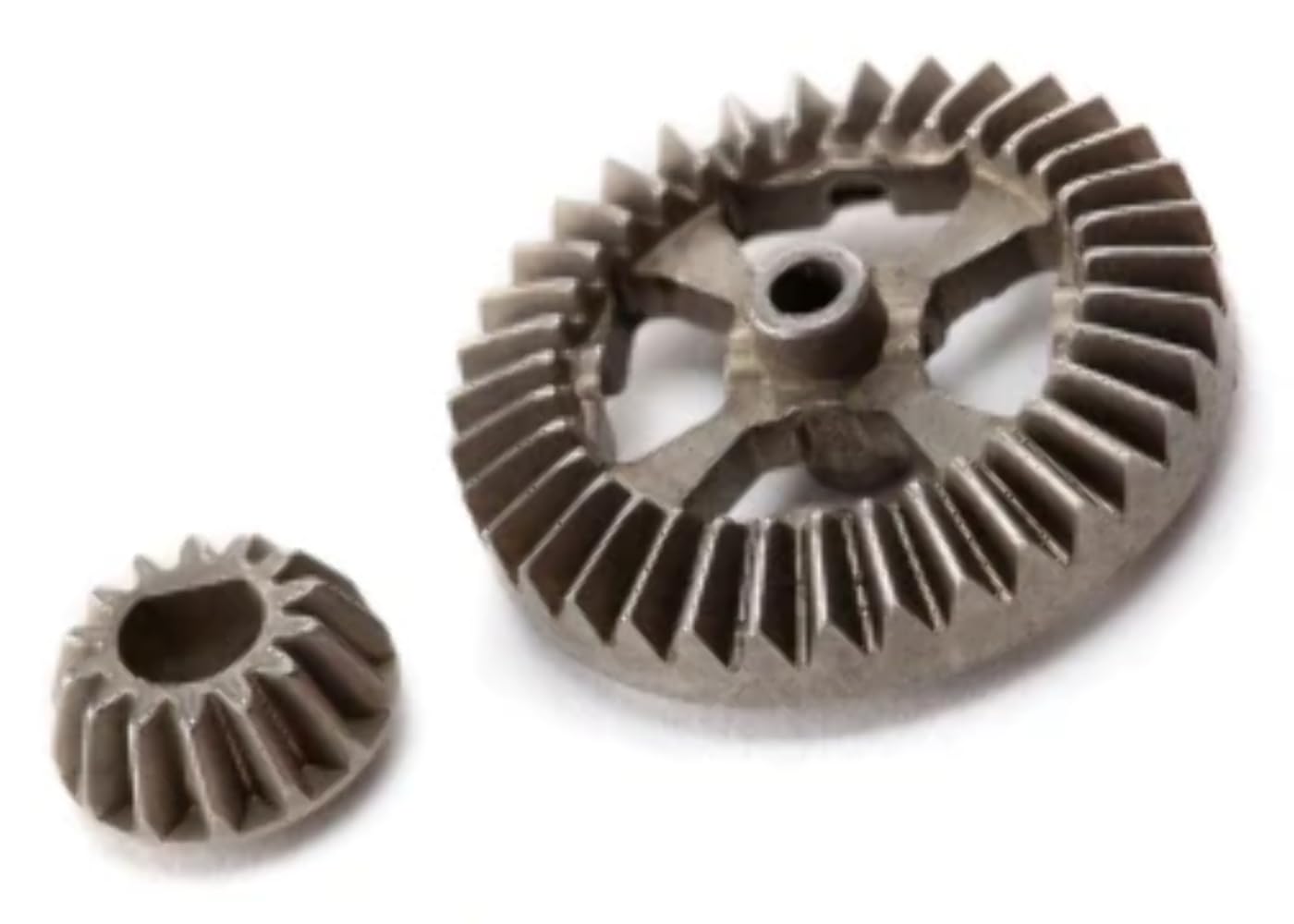
What is a ring gear and how does it work?
A ring gear is a type of gear that features teeth on the outer perimeter of a circular ring-shaped component. It is commonly used in various mechanical systems and applications. Here’s a detailed explanation of what a ring gear is and how it works:
A ring gear, also known as an annular gear or internal gear, is a gear with teeth on the inside circumference of a circular ring. It is designed to mesh with a pinion gear or another gear that has teeth on the outside. The combination of a ring gear and a pinion gear forms a gear set, enabling the transmission of rotational motion and torque between the two gears.
Here’s how a ring gear works:
- Tooth Engagement: When a ring gear and a pinion gear are brought together, the teeth of the pinion gear mesh with the teeth of the ring gear. The teeth of the pinion gear enter the spaces between the teeth of the ring gear, creating a mechanical connection between the two gears.
- Motion Transmission: As the driving gear (such as the pinion gear) rotates, it transfers rotational motion to the ring gear. The teeth of the driving gear push against the teeth of the ring gear, causing the ring gear to rotate in the opposite direction. This rotational motion can be used to drive other components or systems connected to the ring gear.
- Torque Transfer: The meshing of the teeth between the ring gear and the driving gear allows for the transfer of torque. Torque is the rotational force or twisting force applied to a gear. As the driving gear exerts torque on the ring gear through the meshing teeth, the ring gear experiences a torque load. This torque load can be transmitted to other components or systems connected to the ring gear.
- Gear Ratio: The gear ratio between the ring gear and the driving gear determines the speed and torque relationship between the two gears. The gear ratio is defined as the ratio of the number of teeth on the ring gear to the number of teeth on the driving gear. By changing the size or number of teeth on either the ring gear or the driving gear, the gear ratio can be adjusted to achieve the desired speed or torque output.
- Load Distribution: The ring gear distributes the load over a larger area compared to other types of gears. This load distribution characteristic allows the ring gear to handle higher loads and torque. The design of the ring gear and its tooth profile ensures that the load is evenly distributed across the surface of the gear, enhancing its durability and reducing the risk of premature wear or failure.
Ring gears are commonly used in various applications, including automotive transmissions, differential systems, planetary gear systems, industrial machinery, and power transmission equipment. They provide advantages such as compactness, high torque capacity, load distribution, and the ability to achieve high gear ratios.
It’s important to note that the design and characteristics of ring gears may vary depending on the specific application and requirements. Factors such as tooth profile, material selection, lubrication, and manufacturing techniques are carefully considered to ensure optimal performance and durability of the ring gear.


editor by CX 2024-01-04