Product Description
We Are Precision Metal Parts Manufacturer And We Providing Custom Processing Service. Send Us Drawings, We Will Feedback You Quotation Within 24 Hours
Precision Parts Display
Click Here Get More Information
Our Advantages
Equipment
3-axis, 4-axis and full 5-axis processing equipment, CNC lathe, centering machine, turning and milling compound, wire cutting, EDM, grinding, etc
Processing
CNC machining, CNC Turning, CNC Milling, Welding, Laser Cutting, Bending, Spinning, Wire Cutting, Stamping, Electric Discharge Machining (EDM), Injection Molding
Materials
Aluminum, metal, steel, metal, plastic, metal, brass, bronze, rubber, ceramic, cast iron, glass, copper, titanium, metal, titanium, steel, carbon fiber, etc
Tolerance
+/-0.01mm, 100% QC quality inspection before delivery, can provide quality inspection form
Quality Assurance
ISO9001:2015, ISO13485:2016, SGS, RoHs, TUV
Tolerance
Surface Treatment
| Aluminum parts | Stainless Steel parts | Steel parts | Brass parts |
| Clear Anodized | Polishing | Zinc Plating | Nickel Plating |
| Color Anodized | Passivating | Oxide black | chrome plating |
| Sandblast Anodized | Sandblasting | Nickel Plating | Electrophoresis black |
| Chemical Film | Laser engraving | Chrome Plating | Oxide black |
| Brushing | Electrophoresis black | Carburized | Powder coated |
| Polishing | Oxide black | Heat treatment |
Machining Workshop
Production Process
Quality Guarantee
Click Here Get Free Quotation
Application industry
CNC Machining Parts Can Be Used in Many Industry
Aerospace/ Marine/ Metro/ Motorbike/ Automotive industries, Instruments & Meters, Office equipments, Home appliance, Medical equipments, Telecommunication, Electrical & Electronics, Fire detection system, etc
Areospace
Cylinder Heads, Turbochargers, Crankshafts, Connecting Rods Pistons, Bearing Caps, CV Joints, Steering Knuckles, Brake Calipers,Gears,Differential Housing, Axle Shafts
Auto&Motorcycle
Cylinder Heads, Turbochargers, Crankshafts, Connecting Rods Pistons,Bearing Caps, CV Joints, Steering Knuckles, Brake Calipers,Gears, Differential Housing, Axle Shafts
Energy
Drill Pipes and Casing, Impellers Casings, Pipe Control Valves, Shafts, Wellhead Equipment, Mud Pumps, Frac Pumps, Frac Tools,Rotor Shafts and disc
Robotics
Custom robotic end-effectors, Low-volume prototype, Pilot, Enclosures, Custom tooling, Fixturing
Medical Industry
Rotary Bearing Seal Rings for CHINAMFG Knife,CT Scanner Frames,Mounting Brackets,Card Retainers for CT Scanners,Cooling Plenums for CT Scanners,Brackets for CT Scanners,Gearbox Components,Actuators,Large Shafts
Home Appliances
Screws, hinges, handles, slides, turntables, pneumatic rods, guide rails, steel drawers
Certifications
FAQ
Q1. What kind of production service do you provide?
CNC machining, CNC Turning, CNC Milling, Welding, Laser Cutting, Bending, Spinning, Wire Cutting, Stamping, Electric Discharge Machining (EDM), Injection Molding, Simple Assembly and Various Metal Surface Treatment.
Q2. How about the lead time?
Mould : 3-5 weeks
Mass production : 3-4 weeks
Q3. How about your quality?
♦Our management and production executed strictly according to ISO9001 : 2008 quality System.
♦We will make the operation instruction once the sample is approval.
♦ We will 100% inspect the products before shipment.
♦If there is quality problem, we will supply the replacement by our shipping cost.
Q4. How long should we take for a quotation?
After receiving detail information we will quote within 24 hours
Q5. What is your quotation element?
Drawing or Sample, Material, finish and Quantity.
Q6. What is your payment term?
Mould : 50% prepaid, 50% after the mould finish, balance after sample approval.
Goods : 50% prepaid, balance T/T before shipment.
/* March 10, 2571 17:59:20 */!function(){function s(e,r){var a,o={};try{e&&e.split(“,”).forEach(function(e,t){e&&(a=e.match(/(.*?):(.*)$/))&&1
| Application: | Motor, Electric Cars, Motorcycle, Machinery, Marine, Toy, Agricultural Machinery, Car, Aerospace/ Marine/Automotive/Medical Equipments |
|---|---|
| Hardness: | Soft Tooth Surface |
| Gear Position: | External Gear |
| Manufacturing Method: | Machining,Milling,Stamping,Laser Cutting,etc |
| Toothed Portion Shape: | Spur Gear |
| Material: | Stainless Steel |
| Samples: |
US$ 0.8/Piece
1 Piece(Min.Order) | |
|---|
| Customization: |
Available
| Customized Request |
|---|
What lubrication is required for helical gears?
Proper lubrication is essential for the optimal performance and longevity of helical gears. The lubrication requirements for helical gears depend on factors such as the operating conditions, gear materials, and manufacturer recommendations. Here’s a detailed explanation of the lubrication considerations for helical gears:
- Lubricant Selection: The choice of lubricant for helical gears should be based on factors such as operating temperature, load, speed, and environmental conditions. Commonly used lubricants for helical gears include mineral oils, synthetic oils, and greases. Consult the gear manufacturer’s specifications or industry standards to determine the appropriate lubricant viscosity and type for your specific application.
- Viscosity: The lubricant viscosity is an important parameter that influences the lubricating film thickness and the ability to separate the gear surfaces. The viscosity should be selected based on the operating conditions, taking into account factors such as temperature, speed, and load. Higher viscosity lubricants are typically used for heavy-duty applications or high-temperature environments, while lower viscosity lubricants may be suitable for lighter loads or lower speeds.
- Extreme Pressure (EP) Additives: Helical gears, especially those operating under high loads or with high sliding velocities, may benefit from lubricants containing extreme pressure (EP) additives. EP additives help to reduce friction and wear by forming a protective film on the gear surfaces, preventing metal-to-metal contact and minimizing the risk of scuffing or scoring. EP additives are particularly important for helical gears in industrial machinery, automotive transmissions, and gearboxes.
- Lubrication Method: The lubrication method for helical gears can vary depending on the gear design and application. Common methods include splash lubrication, oil bath lubrication, forced circulation systems, and oil mist lubrication. The lubrication method should ensure that an adequate amount of lubricant reaches the gear mesh to provide proper lubrication, cooling, and debris removal during operation.
- Frequency of Lubrication: Regular lubrication maintenance is crucial for helical gears. The lubrication intervals should be determined based on factors such as the gear operating conditions, lubricant type, and gear manufacturer recommendations. Periodic inspections should be conducted to monitor the lubricant condition, check for contamination or degradation, and replenish or replace the lubricant as needed.
- Proper Lubricant Application: When applying the lubricant to helical gears, ensure that the gear teeth and bearings are adequately coated. Pay attention to reaching areas of high friction and contact, such as the gear mesh and tooth roots. Follow the gear manufacturer’s recommendations or guidelines for the proper lubrication technique, which may involve methods such as oil bath immersion, drip lubrication, or centralized lubrication systems.
- Contamination Control: Contamination can significantly affect the performance and lifespan of helical gears. Take measures to prevent the ingress of contaminants such as dirt, dust, moisture, and metal particles into the gear system. Use proper sealing arrangements, filtration systems, and regular maintenance practices to maintain a clean and contamination-free lubrication environment.
It is important to note that the lubrication requirements may vary depending on specific gear designs, materials, and operating conditions. Always refer to the gear manufacturer’s recommendations, industry standards, and consult with lubrication experts or engineers to determine the most suitable lubrication approach for your helical gear application.
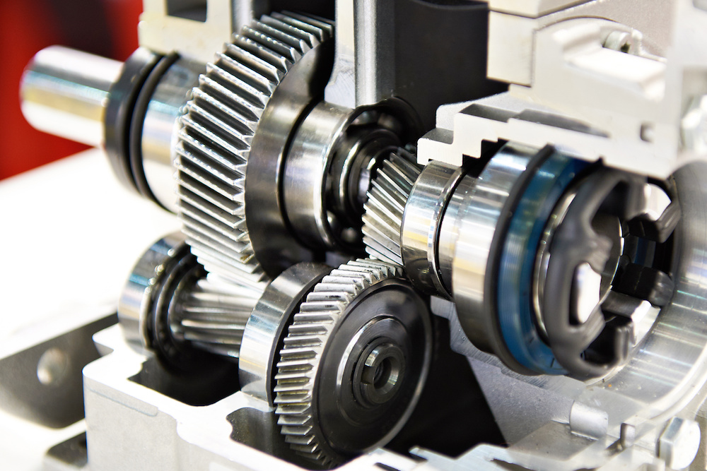
How do you address noise and vibration issues in a helical gear system?
In a helical gear system, addressing noise and vibration issues is crucial to ensure smooth and quiet operation, minimize component wear, and enhance overall system performance. Here’s a detailed explanation of how to address noise and vibration issues in a helical gear system:
- Proper Gear Design: The design of the helical gears can significantly impact noise and vibration levels. Design considerations such as the helix angle, tooth profile modification, and gear tooth contact pattern optimization can help minimize gear noise and vibration. A well-designed gear system with proper tooth geometry and accurate alignment reduces the likelihood of gear meshing irregularities that contribute to noise and vibration.
- Precision Manufacturing: High-quality manufacturing processes are essential to minimize noise and vibration in helical gear systems. Precise gear cutting techniques, such as hobbing or grinding, ensure accurate tooth profiles, which help reduce gear meshing deviations and associated noise. Additionally, maintaining tight manufacturing tolerances and surface finishes on gear components can help minimize vibration caused by irregularities or imperfections.
- Alignment and Assembly: Proper alignment and assembly of the helical gears are critical to minimize noise and vibration. Ensuring precise alignment of the gear shafts and gear meshing is essential to achieve optimal contact between the gear teeth. The use of alignment tools, such as dial indicators or laser alignment systems, can aid in achieving accurate alignment. Additionally, proper assembly techniques, including appropriate gear backlash and preload adjustment, can help minimize noise and vibration by optimizing gear meshing conditions.
- Optimal Lubrication: Proper lubrication is vital for reducing noise and vibration in a helical gear system. Adequate lubrication creates a thin film between the gear teeth, minimizing friction and wear. The lubricant also helps to dampen vibrations and dissipate heat generated during gear operation. Using the correct lubricant type, viscosity, and maintaining proper lubricant levels are essential for noise and vibration control.
- Stiffness of Gearbox Housing: The stiffness and rigidity of the gearbox housing influence noise and vibration levels in a helical gear system. A robust and well-designed housing structure helps to minimize the transmission of vibrations from the gears to the surrounding environment. It is important to ensure that the gearbox housing is adequately braced and supported to reduce resonances and vibrations that can contribute to noise.
- Vibration Damping: Implementing vibration damping techniques can help mitigate noise and vibration in a helical gear system. This can include the use of vibration-absorbing materials, such as elastomers or damping pads, at appropriate locations within the gear system. These materials help absorb and dissipate vibrations, reducing noise transmission and minimizing gear system resonance.
- Condition Monitoring and Maintenance: Regular condition monitoring and maintenance practices are essential for identifying and addressing noise and vibration issues in a helical gear system. Periodic inspections, including vibration analysis, can detect any abnormal vibration patterns or wear indications. Timely maintenance, such as addressing misalignment, worn components, or inadequate lubrication, can prevent further deterioration and reduce noise and vibration levels.
By implementing these measures, engineers can effectively address noise and vibration issues in a helical gear system, resulting in quieter operation, reduced component wear, and improved overall system performance.

What is a helical gear and how does it work?
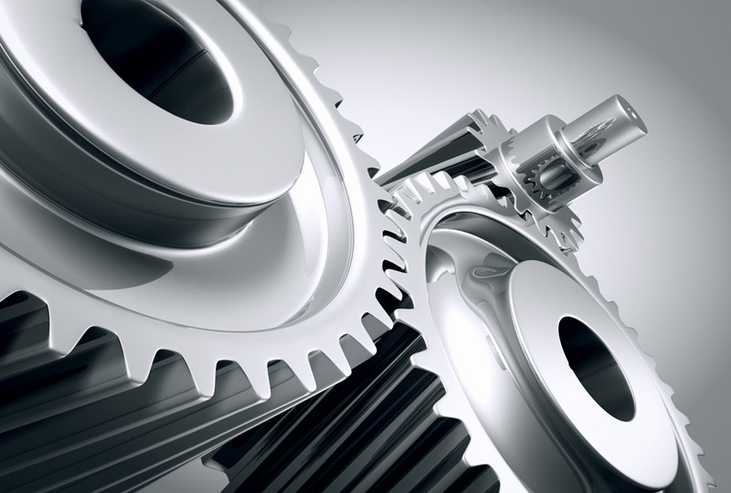
A helical gear is a type of cylindrical gear with teeth that are cut at an angle to the gear axis. It is widely used in various mechanical systems to transmit power and motion between parallel shafts. Here’s a detailed explanation of helical gears and their working principles:
A helical gear consists of a cylindrical shape with teeth that are cut in a helical pattern around the gear’s circumference. The teeth of a helical gear are not perpendicular to the gear axis but are instead aligned at an angle, forming a helix shape. This helix angle allows for gradual engagement and disengagement of the gear teeth, resulting in smoother and quieter operation compared to spur gears.
The working principle of a helical gear involves the transfer of rotational motion and power between parallel shafts. When two helical gears mesh together, their helical teeth gradually come into contact, causing a sliding action as the gears rotate. This sliding action creates both axial and radial forces on the teeth, resulting in a thrust load along the gear axis.
As the helical gears rotate, the sliding action between the teeth causes a force component along the gear axis. This axial force is responsible for generating the thrust load on the gear, which must be properly supported by suitable thrust bearings or other means to ensure smooth and efficient operation.
The helical gear design offers several advantages:
- Smooth and Quiet Operation: The helical teeth engagement allows for a gradual contact between the gear teeth, reducing impact and noise during operation. This results in smoother and quieter gear performance compared to spur gears.
- Increased Load-Carrying Capacity: The helical gear design provides greater tooth contact compared to spur gears. This increased contact area allows helical gears to transmit higher loads and handle greater torque without experiencing excessive wear or tooth failure.
- Parallel Shaft Operation: Helical gears are primarily used for transmitting power and motion between parallel shafts. By meshing two helical gears on parallel shafts, rotational motion can be efficiently transmitted from one shaft to the other with a constant speed ratio.
- Ability to Transmit Motion at Various Angles: While helical gears are commonly used for parallel shaft applications, they can also be used to transmit motion at non-parallel shaft angles by using a combination of helical gears or by incorporating additional components such as bevel gears.
It is important to consider a few factors when using helical gears:
- Helix Angle: The helix angle determines the degree of tooth engagement and sliding action. A higher helix angle increases the smoothness of operation but also introduces a larger axial force and thrust load on the gear.
- Direction of Helix: Helical gears can have either a right-hand or left-hand helix. When two helical gears mesh, they must have opposite helix directions to ensure proper engagement.
- Lubrication: Due to the sliding action between helical gear teeth, proper lubrication is crucial to minimize friction, wear, and heat generation. Adequate lubrication helps ensure the longevity and efficiency of the gear system.
In summary, a helical gear is a cylindrical gear with teeth cut in a helical pattern. It operates by gradually engaging and disengaging the teeth, resulting in smooth and quiet operation. Helical gears are widely used in various mechanical systems for parallel shaft applications, providing high load-carrying capacity and efficient power transmission.


editor by CX 2023-12-25